vii
List of Figures
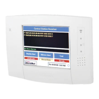
Figure 3–1: MX8000 Front View ........................................................................................................................................3–2
Figure 3–2: MX8000 Front View Without Front Plate Attached ....................................................................................3–2
Figure 3–3: MX8000 Rear View.........................................................................................................................................3–2
Figure 3–4: Rack Mount Enclosure, Front View..............................................................................................................3–3
Figure 3–5: Rack Mount Enclosure, Rear View...............................................................................................................3–4
Figure 3–6: Line Card Locations........................................................................................................................................3–5
Figure 3–7: Line Card Position and Components ...........................................................................................................3–6
Figure 3–8: Parallel Printer Cable Connection to MX8000 ............................................................................................3–8
Figure 3–9: Wiring Sequence For Parallel Printer Port Interface..................................................................................3–8
Figure 3–10: MX8000 Remote Alert Output/Backup Battery Connection....................................................................3–9
Figure 3–11: CPU, PS, User Interface Assembly Retaining Screw Locations .........................................................3–10
Figure 3–12: Side View of CPU, PS, User Interface Assembly ..................................................................................3–10
Figure 3–13: Outlet Voltage Measurement Points ........................................................................................................3–11
Figure 3–14: Battery Connections ...................................................................................................................................3–11
Figure 3–15: 25-Pin Null Modem Cable Connection ....................................................................................................3–12
Figure 3–16: 9-Pin Null Modem Cable Connection.......................................................................................................3–12
Figure 3–17: MX8000 Master/Slave Receiver Linking Cabling Connections............................................................3–13
Figure 3–18: SBUS Receiver Linking Cable ..................................................................................................................3–14
Figure 4–1: MX8000 Front Panel.......................................................................................................................................4–1
Figure 4–2: Touchpad Layout ............................................................................................................................................4–1
Figure 4–3: VFD Display.....................................................................................................................................................4–3
Figure 4–4: Power-up Routine ...........................................................................................................................................4–4
Figure 4–5: Main Menu Display .........................................................................................................................................4–7
Figure 4–6: Main Menu Controls .......................................................................................................................................4–8
Figure 4–7: View of a Call History Screen........................................................................................................................4–8
Figure 4–8: System History Display Sequence ...............................................................................................................4–9
Figure 4–9: System Information Display...........................................................................................................................4–9
Figure 4–10: Setting Time and Date Program Sequence ............................................................................................4–10
Figure 4–11: System Restart Display .............................................................................................................................4–10
Figure 4–12: Print Menu Items.........................................................................................................................................4–11
Figure 4–13: Print Report Menu Items............................................................................................................................4–12
Figure 4–14: Call History Options....................................................................................................................................4–12
Figure 4–15: System Configuration Print Items.............................................................................................................4–13
Figure 4–16: Event Format Menu Items .........................................................................................................................4–14
Figure 4–17: Program Menu Items..................................................................................................................................4–16
Figure 4–18: Diagnostics Menu Items ............................................................................................................................4–16
Figure 4–19: Message Queue Level ...............................................................................................................................4–17
Figure 4–20: Event Log Display.......................................................................................................................................4–17
Figure 4–21: Diagnostic Formats.....................................................................................................................................4–17
Figure 4–22: Select LC Debug Mode by Line Card ......................................................................................................4–17
Figure 4–23: Line Statistics Display ................................................................................................................................4–18
Figure 4–24: Port Status View of Serial Port .................................................................................................................4–18
Figure 4–25: Parallel Port Status View ...........................................................................................................................4–18
Figure 4–26: Phone Connector Pin-Out and Listen-in Wiring Diagram .....................................................................4–20
Figure 5–1: Programming Controls ...................................................................................................................................5–2
Figure 5–2: Program Menu Choices .................................................................................................................................5–2
Figure 5–3: General Options Display................................................................................................................................5–2
Figure 5–4: Normal Operating Mode Display Indicating Manual Operation................................................................5–6
Figure 5–5: View of Display Options .................................................................................................................................5–7
Figure 5–6: Communications Options Menu..................................................................................................................5–12
Figure 5–7: Initialization String Display...........................................................................................................................5–16
Figure 5–8: System Options Display...............................................................................................................................5–22
Figure 5–9: Message Queue Display..............................................................................................................................5–25
Figure 5–10: Slave List Display .......................................................................................................................................5–26
Figure 5–11: Virtual Receiver/Line Numbers Display...................................................................................................5–27