Connect the Timing Analyzer
Note If you have a termination adapter, HP part number 01650-63203, connect
the adapter between Pod 3 of the logic analyzer and J2 of the training
board, then go to the next page to put the analyzer into state and timing
modes.
1
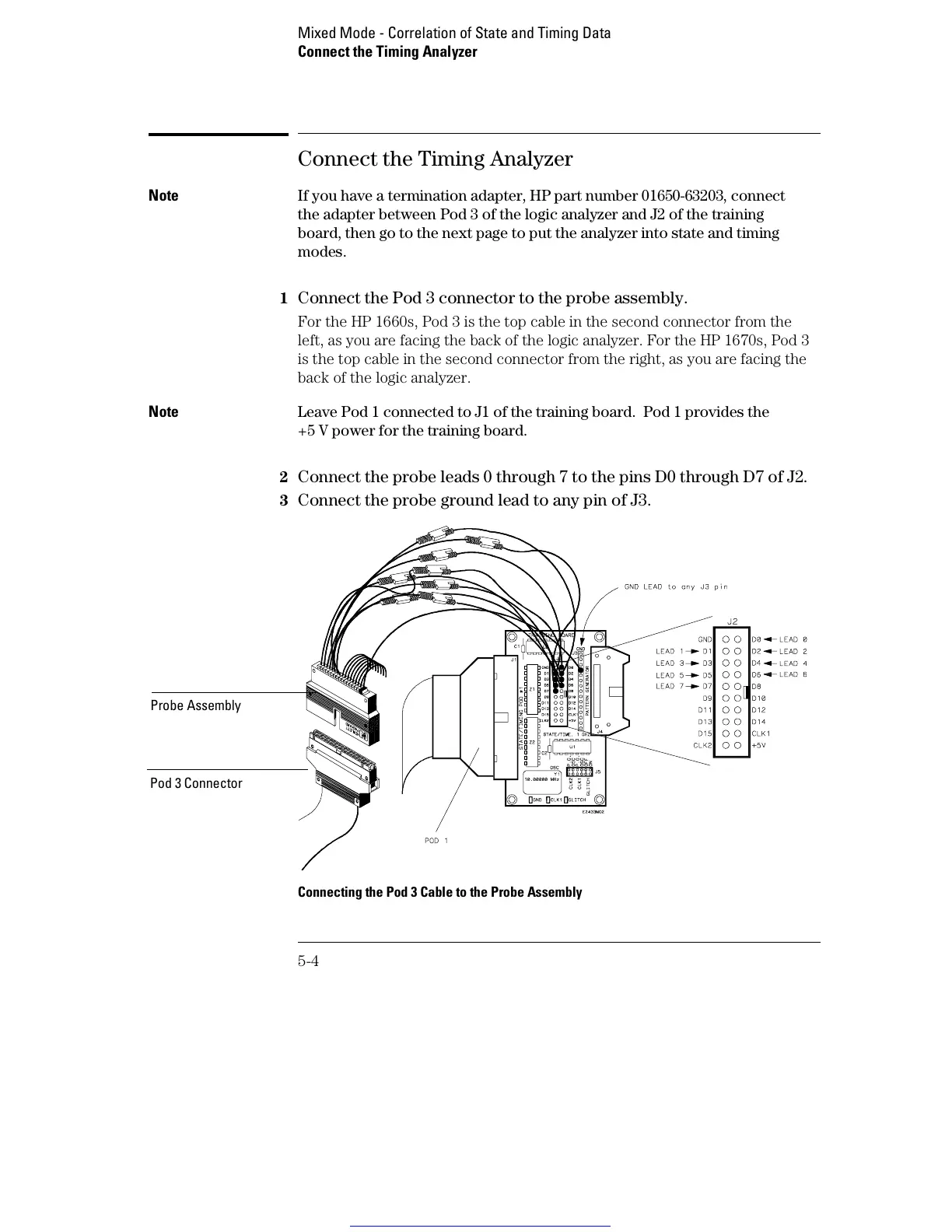
Connect the Pod 3 connector to the probe assembly.
For the HP 1660s, Pod 3 is the top cable in the second connector from the
left, as you are facing the back of the logic analyzer. For the HP 1670s, Pod 3
is the top cable in the second connector from the right, as you are facing the
back of the logic analyzer.
Note Leave Pod 1 connected to J1 of the training board. Pod 1 provides the
+5 V power for the training board.
2
Connect the probe leads 0 through 7 to the pins D0 through D7 of J2.
3 Connect the probe ground lead to any pin of J3.
Connecting the Pod 3 Cable to the Probe Assembly
Probe Assembly
Pod 3 Connector
Mixed Mode - Correlation of State and Timing Data
Connect the Timing Analyzer
5-4
Get other manuals https://www.bkmanuals.com

 Loading...


