Frequency Drift
Minute changes in frequency accuracy and stability can occur as a result of temperature and
aging (on the order of parts per million). If you require greater frequency accuracy, do the
following:
w
Override the internal crystal with a high-stability external source, frequency standard, or (if
your analyzer is equipped with Option
lD5)
use the internal frequency standard.
Performance Verification
You should periodically check the accuracy of the analyzer measurements, by doing the
following:
n perform a measurement verification at least once per year
Refer to the HP 8753E Service
Guide
for the measurement verification procedure.
Reference Plane and Port Extensions
Use the port extension feature to compensate for the phase shift of an extended measurement
reference plane, due to such additions as cables, adapters, and
Bxtures,
after completing an
error-correction procedure (or when there is no active correction).
Using port extensions is similar to using electrical delay. However, using port extensions is the
preferred method of compensating for test
fixture
phase shift.
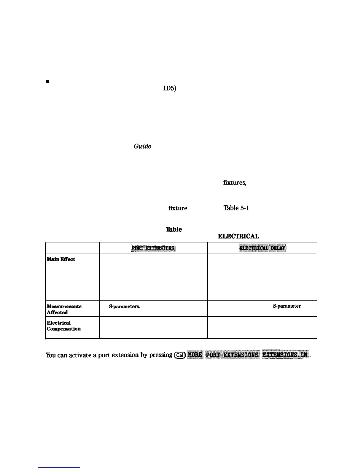
‘Ihble
5-l explains the difference
between port extensions and electrical delay.
‘Ihble
5-1.
Differences between PORT EXTENSIONS and ELECI’IUCAL DELAY
Bldn
meet
i
;
,,
._.
..;
_.
.;
. . .
;.. . . . .
;;
../
:~~~~~~~~..
..__.
. . . . . . . . . . . . . . . . . . .../....
. . . . . . :::m
The end of a cable becomes the test port plane Compensates for the electrical length of a
for all S-parameter measurements.
cable.
Set the cable’s electrical length x 1 for
transmission.
Set the cable’s electrical length x 2 for
reflection.
Meamrements
AlTected
All
S-parameters.
Only the currently selected Sparameter.
EIectrical
Compeneation
Intelligently compensates for 1 times or 2
Only compensates for electrical length.
times the cable’s electrical delay, depending
on which S-parameter is computed.
i_............................_
.,
:
You
cm
a&v&e
apoe
extensionbypressing
Lcal]~~~
~~~~~~~~~~~~~~~~~~~~~.
::::
.._...
..::::..:.......
ii
i
.
.
..A
.~;......~;....~.~;;;._
.A.........
~..~..~~~~ .A.......
.,...:.:.../:.:
:,..
:.
:..
i..,,
.
.
.
.
.
.A..
.
.
.
.
.
.
.
.
.
.
.
.
.
.
.
.
.
.
.
.
.
.
.
.
.
.
.
.
.
.
.
.
.
.
.
.
.
.
.
.
.
..~.... ..A.
.
.
..A.. .A....
v~.;;;:
.
.
.
.._..
Then enter the delay to the reference plane.
Optimizing Measurement Results
63

 Loading...


