11-78 Chapter 11
SCSI Peripherals and I/O Information
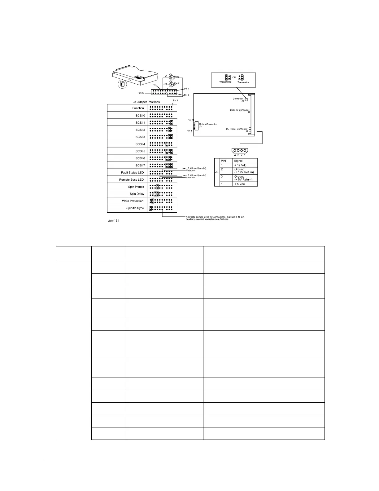
Figure 11-43 A3304A Jumpering (XP32275)
Table 11-32 A3304A J3 Option Jumpers (XP32275L)
Connector Pin-set Function Configuration
J3 1-2 SCSI ID 0 SCSI ID bit 0. Open=0, Jumpered=1
3-4 SCSI ID 1 SCSI ID bit 1. Open=0, Jumpered=1
5-6 SCSI ID 2 SCSI ID bit 1. Open=0, Jumpered=1
7 FLT_OUT L Provides active low connection for
cathode of fault LED.
8 No Connector
9 BSY_OUT L Provides active low connection for
anode of
fault LED.
10 or 19 SPINDLE_SYNC_REF
L
Provides connection for Spindle sync
REF signal.
11 +5 VDC OUT Provides +5 VDC out.
12 Reserved
13-14 Spin Immed. Spin Immed is enabled (jumpered).
15-16 Spin Delay Spin Delay is enabled (jumpered).
17-18 Write Protect Write Protect is enabled (jumpered).

 Loading...