94
BPDU tunneling configuration
Introduction to BPDU tunneling
As a Layer 2 tunneling technology, BPDU tunneling enables Layer 2 protocol packets from geographically
dispersed customer networks to be transparently transmitted over specific tunnels across a service provider
network.
Background
Customers usually use dedicated lines in a service provider network to build their own Layer 2 networks.
As a result, often a customer network consists of parts located at different sides of the service provider
network. As shown in Figure 27, the devices for User A are CE 1 and CE 2, both of which belong to
VLAN 100. User A’s network is divided into network 1 and network 2, which are connected by the
service provider network. When Layer 2 protocol packets cannot be transparently transmitted in the
service provider network, User A’s network cannot implement independent Layer 2 protocol calculation
(for example, STP spanning tree calculation). The Layer 2 protocol calculation in User A’s network is
mixed with that in the service provider network.
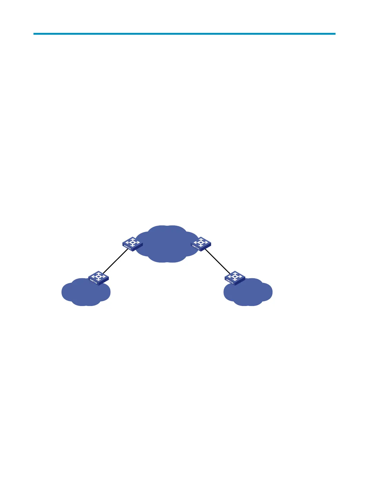
Figure 27 BPDU tunneling application scenario
ISP network
User A network 1
VLAN 100
User A network 2
VLAN 100
CE 1 CE 2
PE 1 PE 2
BPDU tunneling addresses this problem. With BPDU tunneling, Layer 2 protocol packets from customer
networks can be transparently transmitted in the service provider network, as follows:
1. After receiving a Layer 2 protocol packet from User A network 1, PE 1 in the service provider
network encapsulates the packet, replaces its destination MAC address with a specific multicast
MAC address, and then forwards the packet in the service provider network.
2. The encapsulated Layer 2 protocol packet (called bridge protocol data unit, BPDU for short) is
forwarded to PE 2 at the other end of the service provider network, which de-encapsulates the
packet, restores the original destination MAC address of the packet, and then sends the packet to
User A network 2.

 Loading...


