129
Isolate-user-VLAN configuration example
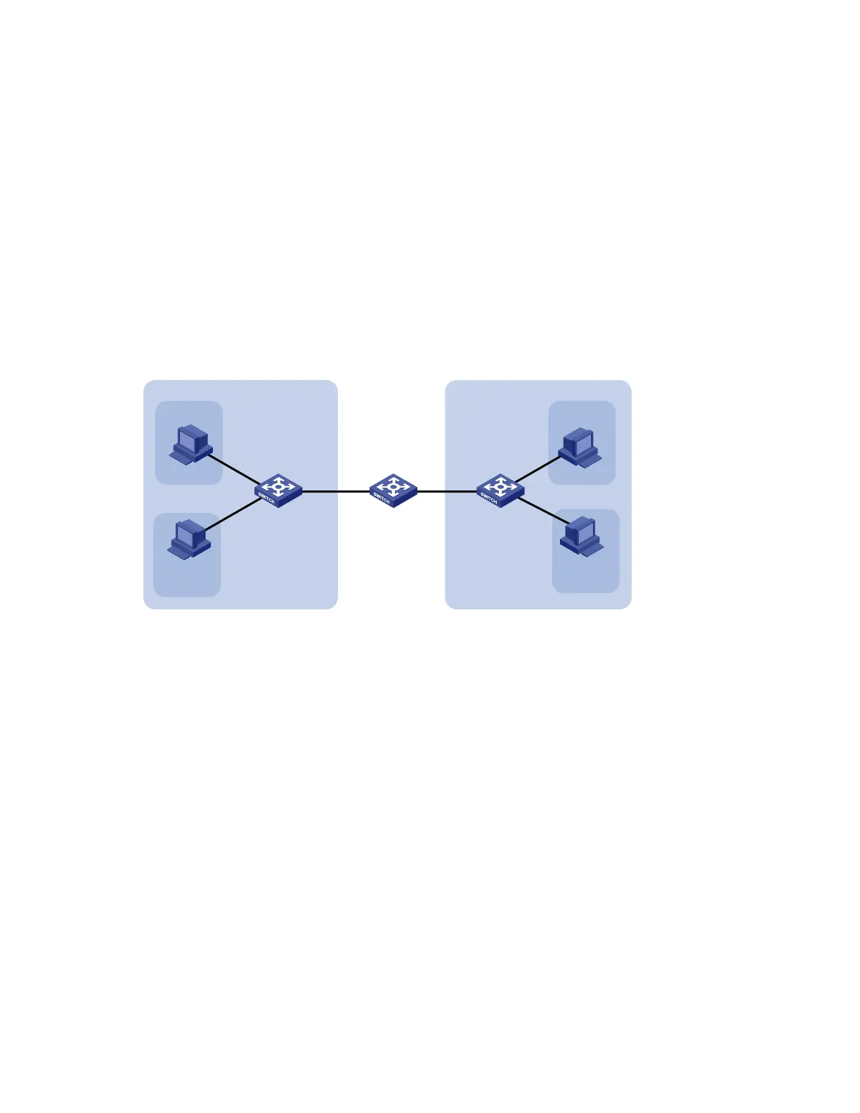
Network requirements
As shown in Figure 39,
Connect Device A to downstream devices Device B and Device C.
Configure VLAN 5 on Device B as an isolate-user-VLAN, assign the uplink port GigabitEthernet
1/0/5 to VLAN 5, and associate VLAN 5 with secondary VLANs VLAN 2 and VLAN 3. Assign
GigabitEthernet 1/0/2 to VLAN 2 and GigabitEthernet 1/0/1 to VLAN 3.
Configure VLAN 6 on Device C as an isolate-user-VLAN, assign the uplink port GigabitEthernet
1/0/5 to VLAN 6, and associate VLAN 6 with secondary VLANs VLAN 3 and VLAN 4. Assign
GigabitEthernet 1/0/3 to VLAN 3 and GigabitEthernet 1/0/4 to VLAN 4.
As far as Device A is concerned, Device B has only VLAN 5 and Device C has only VLAN 6.
Figure 39 Network diagram for isolate-user-VLAN configuration
GE
1
/
0
/
1
GE
1
/
0
/
2
VLAN 5
GE
1
/
03
GE
1
/
0
/
4
VLAN 6
GE1/0/5 GE1/0/5
Device A
Device B
Device C
Host A
Host B
Host C
Host D
VLAN 3
VLAN 2
VLAN 3
VLAN 4
Configuration procedure
The following part provides only the configuration on Device B and Device C.
1. Configure Device B.
# Configure the isolate-user-VLAN.
<DeviceB> system-view
[DeviceB] vlan 5
[DeviceB-vlan5] isolate-user-vlan enable
[DeviceB-vlan5] quit
# Configure the secondary VLANs.
[DeviceB] vlan 2 to 3
# Configure the uplink port GigabitEthernet 1/0/5 to operate in promiscuous mode.
[DeviceB] interface gigabitethernet 1/0/5
[DeviceB-GigabitEthernet1/0/5] port isolate-user-vlan promiscuous
[DeviceB-GigabitEthernet1/0/5] quit
# Assign downlink ports GigabitEthernet 1/0/1 to VLAN 3 and GigabitEthernet 1/0/2 to VLAN 2, and
configure the ports to operate in host mode.
[DeviceB] interface gigabitethernet 1/0/1

 Loading...


