63
Basic concepts in MSTP
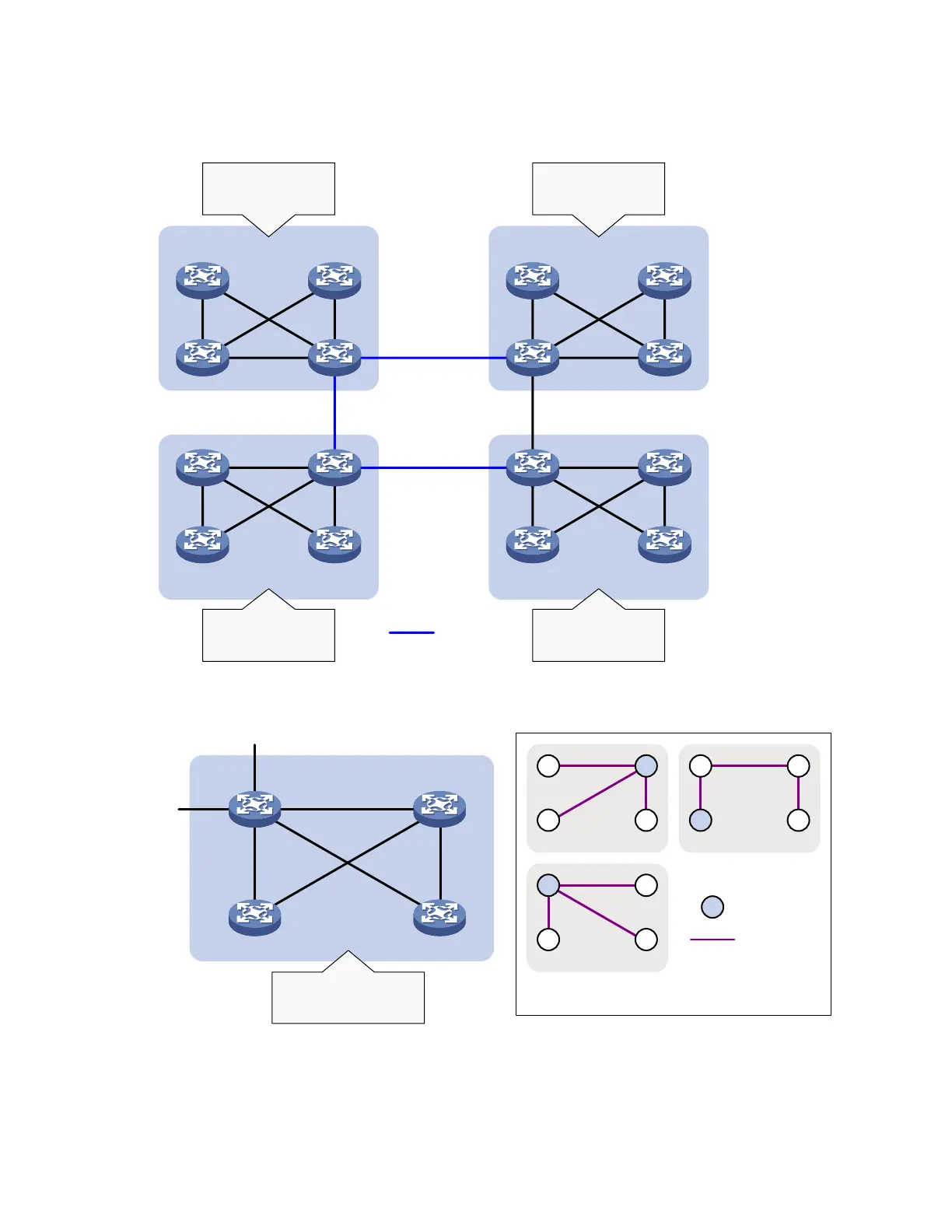
Figure 18 Basic concepts in MSTP
MST region 1
MST region 2 MST region 3
MST region 4
VLAN 1 à MSTI 1
VLAN 2 à MSTI 2
Other VLANs à MSTI 0
VLAN 1 à MSTI 1
VLAN 2 à MSTI 2
Other VLANs à MSTI 0
VLAN 1 à MSTI 1
VLAN 2 à MSTI 2
Other VLANs à MSTI 0
VLAN 1 à MSTI 1
VLAN 2&3 à MSTI 2
Other VLANs à MSTI 0
CST
Figure 19 Network diagram and topology of MST region 3
MST region 3
Device A
Device C
Device B
Device D
VLAN 1 à MSTI 1
VLAN 2&3 à MSTI 2
Other VLANs à MSTI 0
To MST region 4
To MST region 2
BA
C D
MSTI 1
A B
C D
MSTI 0
B
D
MSTI 2
C
A
Regional root
MSTI
Topology of MSTIs in MST region 3
As shown in Figure 18, a switched network comprises four MST regions, and each MST region comprises
four devices running MSTP. Figure 19 shows the networking topology of MST region 3.

 Loading...


