156
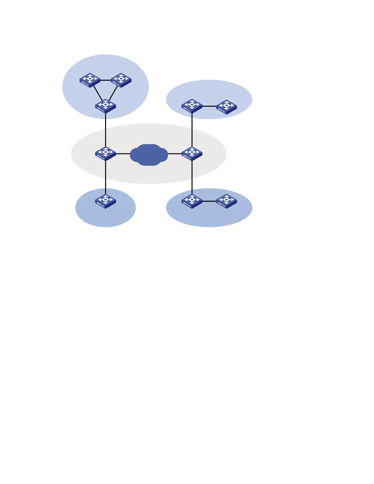
Figure 49 Typical QinQ application scenario
Network
Service provider network
VLAN 1~10
VLAN 1~10
VLAN 1~20 VLAN 1~20
VLAN 3
VLAN 3
VLAN 4 VLAN 4
Customer network A
Customer network A
Customer network BCustomer network B
As shown in Figure 49, customer network A has CVLANs 1 through 10, and customer network B has
CVLANs 1 through 20. The service provider assigns SVLAN 3 for customer network A, and assigns
SVLAN 4 for customer network B. When a tagged Ethernet frame from customer network A arrives at the
edge of the service provider network, the edge switch tags the frame with outer VLAN 3. When a tagged
Ethernet frame from customer network B arrives at the edge of the service provider network, the edge
switch tags it with outer VLAN 4. As a result, no overlap of VLAN IDs among customers exists, and traffic
from different customers can be identified separately.
QinQ frame structure
A QinQ frame is transmitted double-tagged over the service provider network. The inner VLAN tag is the
CVLAN tag, and the outer one is the SVLAN tag that the service provider has allocated to the customer.

 Loading...


