44
NOTE:
In an aggregation group, only ports that have the same port attributes and class-two configurations
(see ‖Configuration classes‖) as the reference port (see ―Reference port‖) can operate as Selected
ports. You must ensure that all member ports have the same port attributes and class-two configurations
as the reference port. The other settings only need to be configured on the aggregate interface, not on
the member ports.
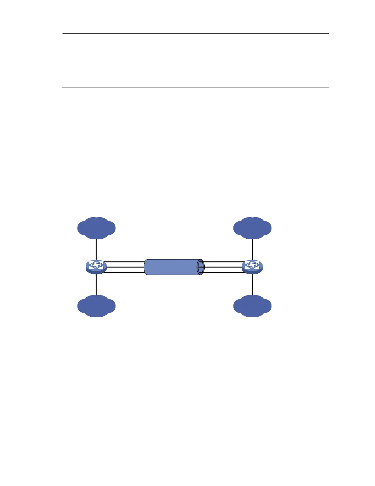
Layer 2 static aggregation configuration example
Network requirements
As shown in Figure 11:
Device A and Device B are connected through their respective Layer 2 Ethernet interfaces
GigabitEthernet 1/0/1 through GigabitEthernet 1/0/3.
Configure a Layer 2 static link aggregation group on Device A and Device B, respectively. Enable
VLAN 10 at one end of the aggregate link to communicate with VLAN 10 at the other end, and
VLAN 20 at one end to communicate with VLAN 20 at the other end.
Enable traffic to be load-shared across aggregation group member ports based on source and
destination MAC addresses.
Figure 11 Network diagram for Layer 2 static aggregation
GE1/0/2
GE1/0/1
GE1/0/3
Link aggregation 1
GE1/0/2
GE1/0/1
GE1/0/3
BAGG1 BAGG1
Device A Device B
VLAN 10
VLAN 20
GE1/0/4
GE1/0/5
VLAN 10
VLAN 20
GE1/0/4
GE1/0/5
Configuration procedure
1. Configure Device A
# Create VLAN 10, and assign port GigabitEthernet 1/0/4 to VLAN 10.
<DeviceA> system-view
[DeviceA] vlan 10
[DeviceA-vlan10] port gigabitethernet 1/0/4
[DeviceA-vlan10] quit
# Create VLAN 20, and assign port GigabitEthernet 1/0/5 to VLAN 20.
[DeviceA] vlan 20
[DeviceA-vlan20] port gigabitethernet 1/0/5
[DeviceA-vlan20] quit
# Create Layer 2 aggregate interface Bridge-Aggregation 1.

 Loading...


