48
AGG AGG Partner ID Select Unselect Share
Interface Mode Ports Ports Type
-------------------------------------------------------------------------------
BAGG1 D 0x8000, 000f-e2ff-0002 3 0 Shar
The output shows that link aggregation group 1 is a load-shared Layer 2 dynamic aggregation group,
and it contains three Selected ports.
# Display the global link-aggregation load-sharing criteria on Device A.
[DeviceA] display link-aggregation load-sharing mode
Link-Aggregation Load-Sharing Mode:
destination-mac address, source-mac address
The output shows that all link aggregation groups created on the device perform load sharing based on
source and destination MAC addresses.
Layer 2 aggregation load sharing configuration example
Network requirements
As shown in Figure 13:
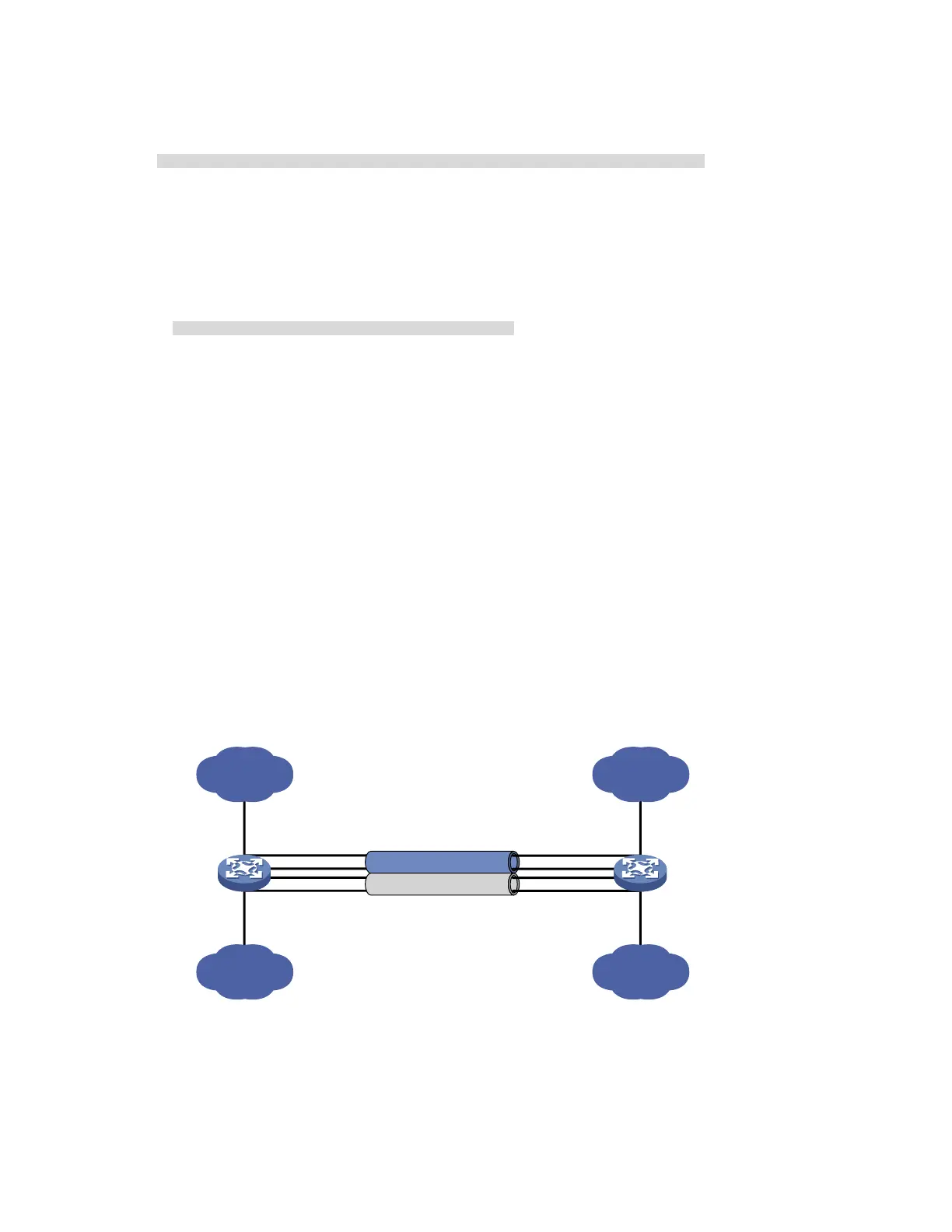
Device A and Device B are connected by their Layer 2 Ethernet interfaces GigabitEthernet 1/0/1
through GigabitEthernet 1/0/4.
Configure two Layer 2 static link aggregation groups (1 and 2) on Device A and Device B
respectively, and enable VLAN 10 at one end of the aggregate link to communicate with VLAN 10
at the other end through Bridge-Aggregation 1, and VLAN 20 at one end to communicate with
VLAN 20 at the other end through Bridge-Aggregation 2.
Configure the load sharing criterion for link aggregation group 1 as the source MAC addresses of
packets and the load sharing criterion for link aggregation group 2 as the destination MAC
addresses of packets to enable traffic to be load-shared across aggregation group member ports.
Figure 13 Network diagram for Layer 2 aggregation load sharing configuration
GE1/0/2
GE1/0/1
GE1/0/3
Link aggregation 1
BAGG1 BAGG1
Device A Device B
Link aggregation 2
GE1/0/4
GE1/0/2
GE1/0/1
GE1/0/3
GE1/0/4
BAGG2 BAGG2
VLAN 10
VLAN 20
GE1/0/5
GE1/0/6
VLAN 10
VLAN 20
GE1/0/5
GE1/0/6
Configuration procedure
1. Configure Device A
# Create VLAN 10, and assign port GigabitEthernet 1/0/5 to VLAN 10.
<DeviceA> system-view

 Loading...


