125
Isolate-user-VLAN configuration
Overview
An isolate-user-VLAN uses a two-tier VLAN structure. In this approach, the following types of VLANs,
isolate-user-VLAN and secondary VLAN, are configured on the same device.
The following are the characteristics of the isolate-user-VLAN implementation:
Isolate-user-VLANs are mainly used for upstream data exchange. An isolate-user-VLAN can be
associated with multiple secondary VLANs. Because the upstream device identifies only the isolate-
user-VLAN and not the secondary VLANs, network configuration is simplified and VLAN resources
are saved.
You can isolate the Layer 2 traffic of different users by assigning the ports connected to them to
different secondary VLANs.
The dynamic MAC addresses entries learned in the isolate-user-VLAN are automatically
synchronized to all the secondary VLANs, and the dynamic MAC address entries learned in a
secondary VLAN are automatically synchronized to the isolate-user-VLAN.
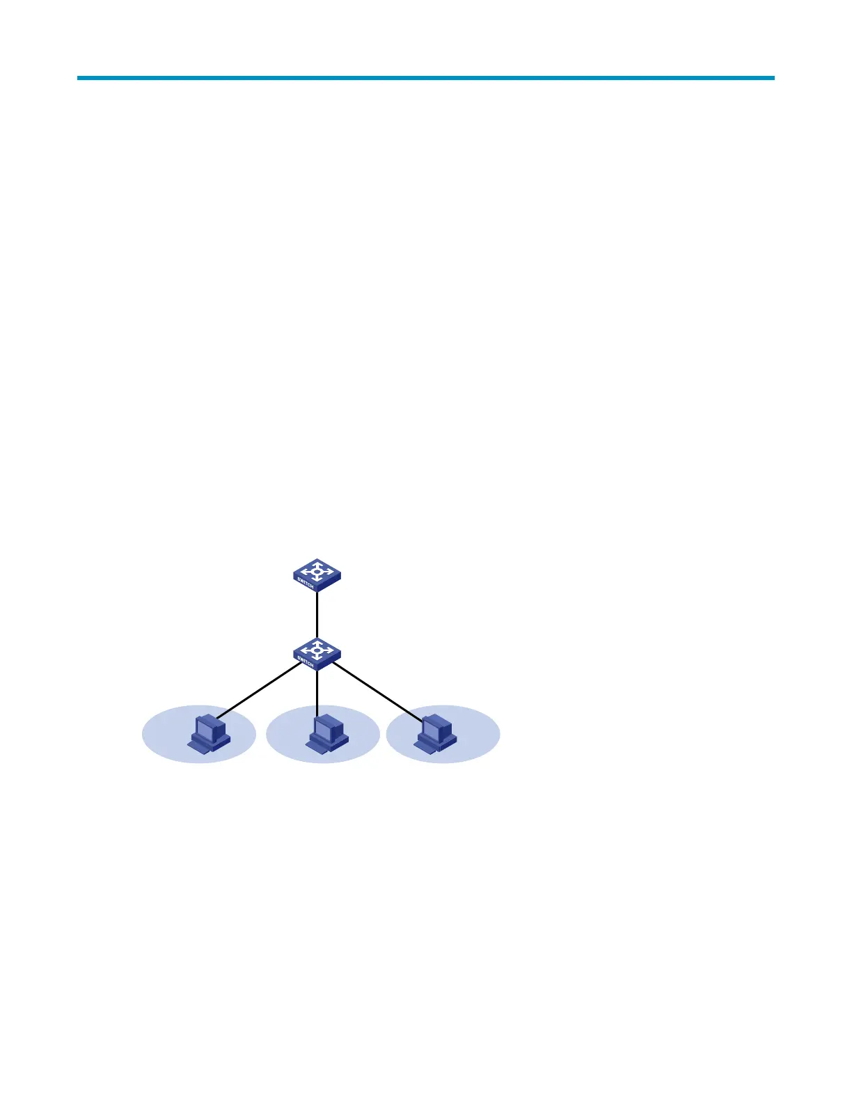
As shown in Figure 38, the isolate-user-VLAN function is enabled on Switch B. VLAN 10 is the isolate-user-
VLAN. VLANs 2, 5, and 8 are secondary VLANs associated with VLAN 10 and are invisible to Switch A.
Figure 38 An isolate-user-VLAN example
VLAN 2 VLAN 5 VLAN 8
VLAN 10
Switch A
Switch B
Configuring isolate-user-VLAN
Configure the isolate-user-VLAN through the following steps:
1. Configure the isolate-user-VLAN.
Assign non-trunk ports to the isolate-user-VLAN and configure these ports as upstream ports.
To enable users in the isolate-user-VLAN to communicate with other networks at Layer 3,
configure a VLAN interface for the isolate-user-VLAN, and configure an IP address for the
isolate-user-VLAN interface.
To enable Layer 3 communication among secondary VLANs associated with the same isolate-
user-VLAN, you must enable local proxy ARP on the upstream device.

 Loading...


