29
Ethernet link aggregation configuration
Overview
Ethernet link aggregation, or simply link aggregation, combines multiple physical Ethernet ports into one
logical link, called an ―aggregate link‖. Link aggregation delivers the following benefits:
Increases bandwidth beyond the limits of any single link. In an aggregate link, traffic is distributed
across the member ports.
Improves link reliability. The member ports dynamically back up one another. When a member port
fails, its traffic is automatically switched to other member ports.
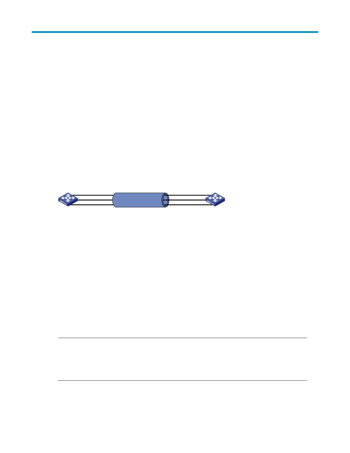
As shown in Figure 7, Device A and Device B are connected by three physical Ethernet links. These
physical Ethernet links are combined into an aggregate link, Link aggregation 1. The bandwidth of this
aggregate link is as high as the total bandwidth of the three physical Ethernet links. At the same time, the
three Ethernet links back up each other.
Figure 7 Diagram for Ethernet link aggregation
GE1/0/2
GE1/0/1
GE1/0/3
Link aggregation 1
GE1/0/2
GE1/0/1
GE1/0/3
Device A Device B
Basic concepts
Aggregation group, member port, aggregate interface
Link aggregation is implemented through link aggregation groups. An aggregation group is a group of
Ethernet interfaces aggregated together, which are called ―member ports‖ of the aggregation group. For
each aggregation group, a logical interface, called an ―aggregate interface‖, is created. To an upper
layer entity that uses the link aggregation service, a link aggregation group appears to be a single
logical link and data traffic is transmitted through the aggregate interface.
When you create an aggregate interface, the switch automatically creates an aggregation group of the
same type and number as the aggregate interface. For example, when you create interface Bridge-
aggregation 1, Layer 2 aggregation group 1 is created.
You can assign Layer 2 Ethernet interfaces only to a Layer 2 aggregation group.
NOTE:
The rate of an aggregate interface equals the total rate of its member ports in the Selected state, and its
duplex mode is the same as the selected member ports. For more information about the states of
member ports in an aggregation group, see ―Aggregation states of member ports in an aggregation
group.‖
Aggregation states of member ports in an aggregation group
A member port in an aggregation group can be in either of the following aggregation states:
Selected: A Selected port can forward user traffic.

 Loading...


