Modem
Control Register (XFCH)
This register controls
the
modem
signals. It also allows
the
HP24540A
to
be set
into
diagnostic mode.
In
the
diagnostic
mode, transmitted data
is
received immediately. The receiver and
transmitter interrupts and
the
modem
control interrupts are fully
operational, allowing
the
interrupts
to
be tested.
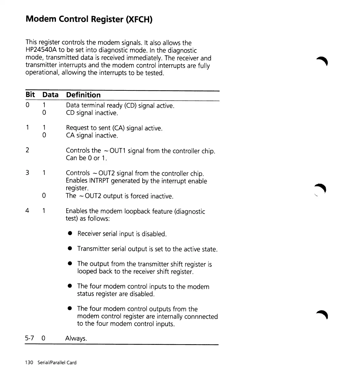
Bit Data Definition
0
1
Data terminal ready
(CD)
signal active.
0
CD
signal inactive.
1
Request
to
sent (CA) signal active.
0 CA signal inactive.
2
Controls
the
--
OUT1
signal
from
the
controller chip.
Can be 0
or
1.
3
Controls
--
GUT2 signal
from
the
controller chip.
Enables
INTRPT
generated by
the
interrupt enable
~
register.
0
The -- OUT2
output
is
forced inactive.
"-
4 Enables
the
modem
loopback feature (diagnostic
test)
as
follows:
•
Receiver serial
input
is
disabled.
• Transmitter serial
output
is
set
to
the
active state.
•
The
output
from
the
transmitter shift register
is
looped back
to
the
receiver shift register.
• The
four
modem
control inputs
to
the
modem
status register are disabled.
• The
four
modem
control outputs
from
the
modem
control register are internally connnected
to
the
four
modem
control inputs.
5-7 0 Always.
130 Serial/Parallel Card