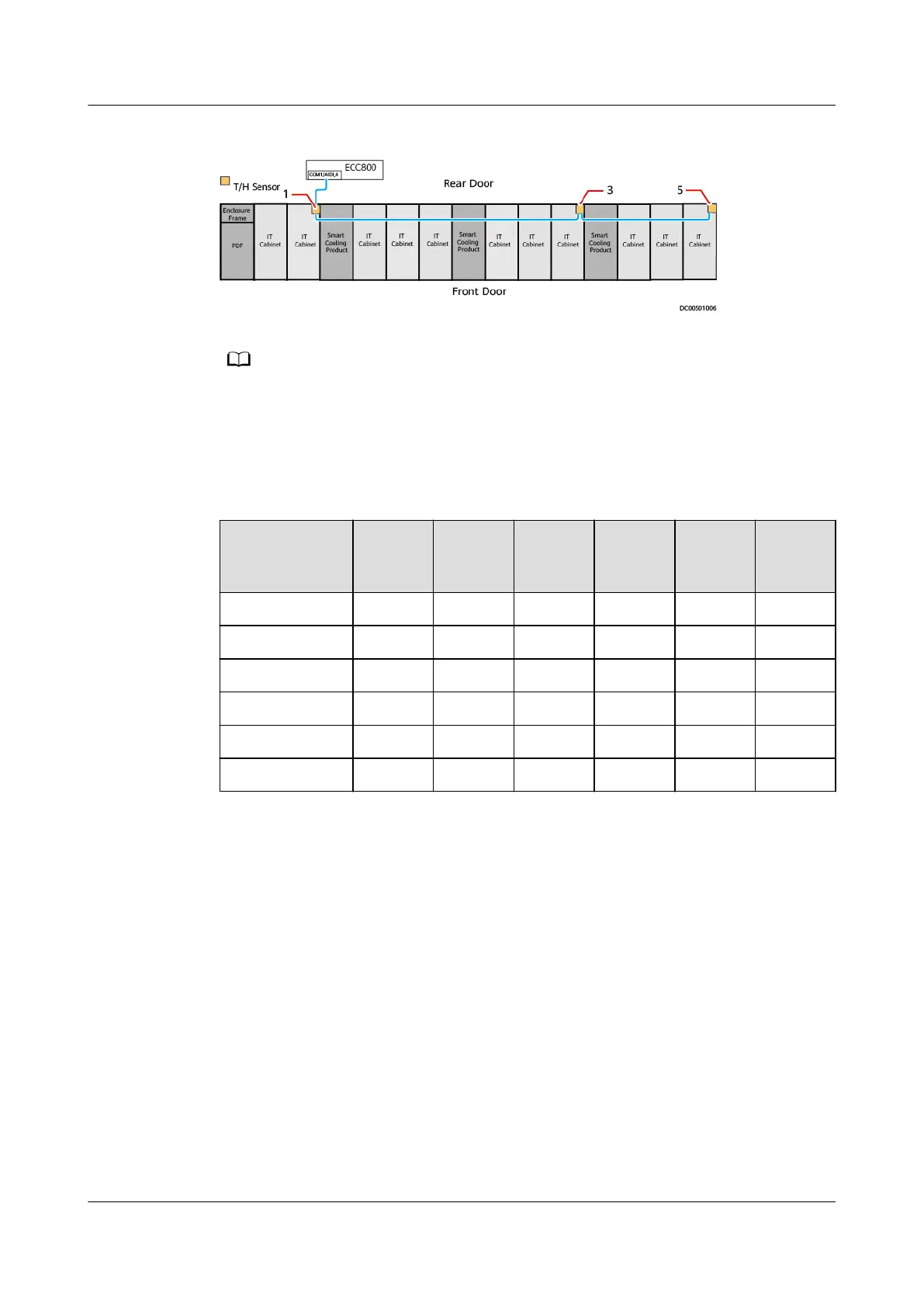
Figure 3-100 DIP switch settings for T/H sensors (hot aisle containment scenario)
● The gures are for reference only. The actual layout depends on the onsite
conguration.
● The numbers 1–6 indicate the DIP switch settings of the T/H sensors.
● An even address indicates a cold aisle, and an odd address indicates a hot aisle.
Table 3-2 DIP switch settings for T/H sensors
T/H Sensor
Address
DIP
Switch
1
DIP
Switch
2
DIP
Switch
3
DIP
Switch
4
DIP
Switch
5
DIP
Switch
6
1 ON OFF OFF OFF OFF OFF
2 OFF ON OFF OFF OFF OFF
3 ON ON OFF OFF OFF OFF
4 OFF OFF ON OFF OFF OFF
5 ON OFF ON OFF OFF OFF
6 OFF ON ON OFF OFF OFF
----End
3.10.12 Installing Remote T/H Sensors for Smart Cooling
Products
3.10.12.1 Rules for Deploying T/H Sensors
Congure T/H sensors based on the number of smart cooling products. For
example, if three smart cooling products are deployed, congure three T/H
sensors.
Procedure
Step 1 Attach the T/H sensors delivered with a smart cooling product to the front door
post of the adjacent IT cabinet.
FusionModule2000-S Smart Modular Data Center
User Manual 3 Hardware Installation
Issue 07 (2022-09-30) Copyright © Huawei Technologies Co., Ltd. 108