4.2 Installing Smart Busbar Cables
For details, see the documents delivered with the equipment, the documents
obtained by scanning the QR code, or
NMW Smart Busbar 2.0 User Manual
.
4.3 Connecting a Monitoring Cable to the Smart ETH
Gateway
Prerequisites
The smart ETH gateway has been installed.
Context
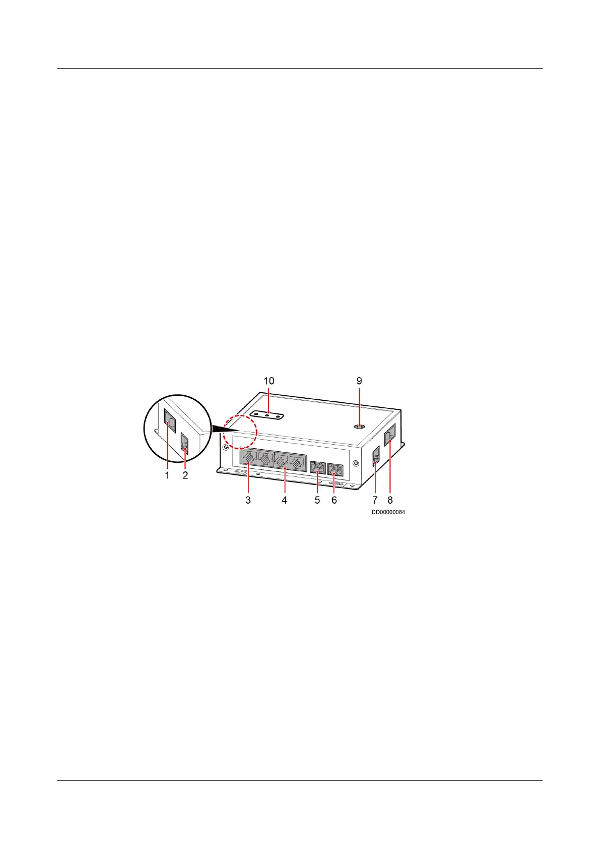
Figure 4-9 shows the external ports on a smart ETH gateway.
Figure 4-9 Ports on a smart ETH gateway
(1) PWR_IN cascading power
port
(2) FE_1 cascading signal port (3) PoE_1–2 ports
(4) PoE_3–4 ports (5) 48V_OUT1 power output
port
(6) 48V_OUT2 power output
port
(7) FE_2 cascading signal port (8) PWR_OUT cascading power
port
(9) BLINK button
(10) Status indicator
Procedure
Step 1 Take out the ground cable from the smart ETH gateway
tting bag and connect
the cable to the ground screw on the smart ETH gateway.
Step 2 Connect the PWR_OUT port on the smart ETH gateway to the 53.5VDC_OUT1 or
53.5VDC_OUT2 port on the ECC800-Pro using a power cable.
FusionModule2000-S Smart Modular Data Center
User Manual 4 System Cabling
Issue 07 (2022-09-30) Copyright © Huawei Technologies Co., Ltd. 124