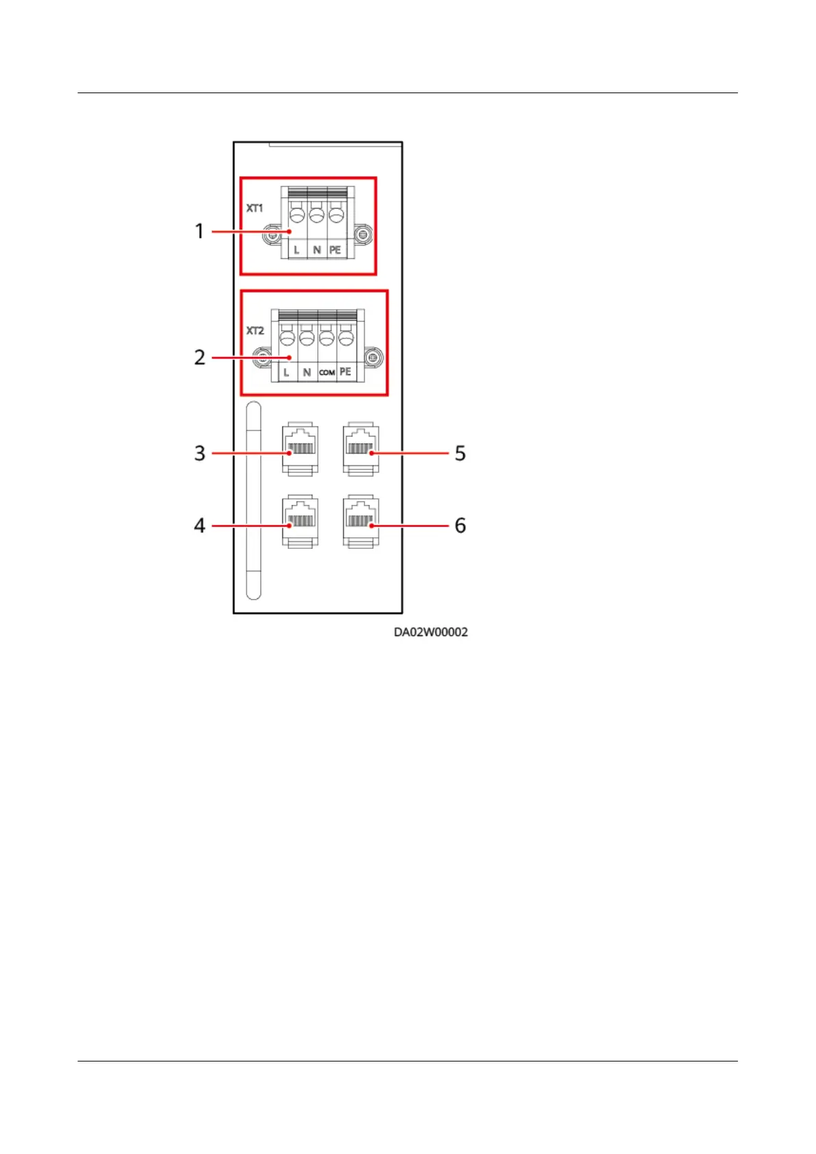
Figure 4-35 Electrical ports on the indoor unit
(1) Main power ports (2) Outdoor unit power ports
(3) Debugging port (4) Communications port
(5) Teamwork control CAN port (6) T/H sensor port
Figure 4-36 shows the cable connections to the smart cooling product. Figure
4-37 shows the cable route between the electrical port on the indoor unit and the
outdoor unit.
FusionModule500 Smart Mini Data Center
User Manual 4 Installation Guide
Issue 02 (2020-12-25) Copyright © Huawei Technologies Co., Ltd. 94