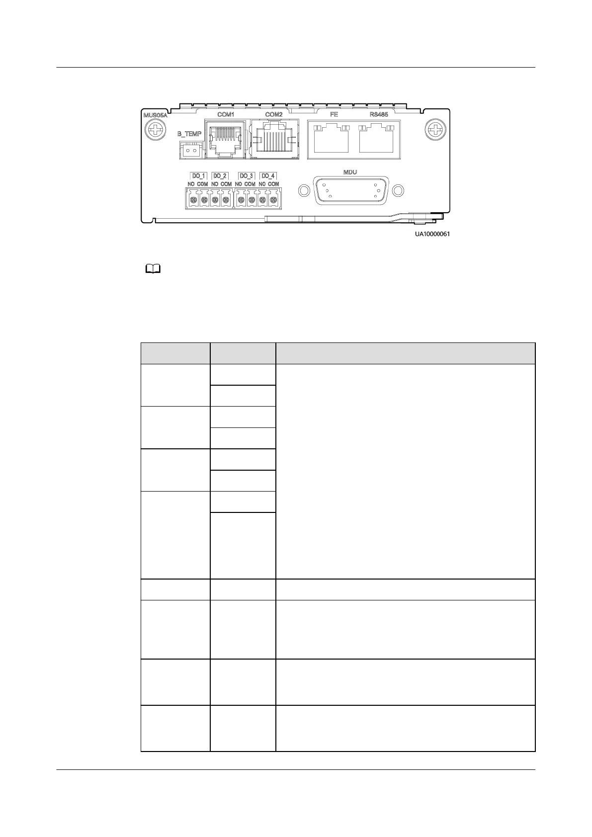
Figure 2-14 Monitoring interface card
The maximum voltage and current of ports DO_1 to DO_4 are 30 V DC, 1 A or 60 V DC, 0.5
A respectively.
Table 2-7 Ports on the monitoring interface card
Port Silk Screen Description
DO_1 NO ● DO_1, DO_2, DO_3, and DO_4 indicate alarm
outputs. The default values are Critical alarm,
Minor alarm, Bypass mode, and Battery mode,
respectively.
● On the LCD, choose System Info > Settings >
System Settings > Dry Contact Set. Set
MUS05A DO_1, MUS05A DO_2, MUS05A DO_3
and MUS05A DO_4 to Disable, Critical alarm,
Minor alarm, Bypass mode, Battery mode, Low
batt. volt., Low battery SOC, Abnormal mains,
Sys maint breaker enable, Sys outp breaker
enable, Maint. breaker closed, No power
supplied, Mains supplies power, ECO mode,
Battery test, and Batt. Volt. Below Thres.
●
Congure power segment settings based on
backup time.
COM
DO_2 NO
COM
DO_3 NO
COM
DO_4 NO
COM
DB26 MDU Provides FE, RS485, I2C, and CAN signals.
Battery
temperatur
e sensor
port
B_TEMP Connects to an indoor battery temperature sensor.
Southbound
communica
tions port 1
COM1 ● Supported protocol: Modbus-RTU
● Connects to a southbound device.
Southbound
communica
tions port 2
COM2 ● Supported protocol: Modbus-RTU
● In use.
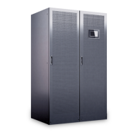
UPS5000-E-(30 kVA–180 kVA)
User Manual (Integrated UPS) 2 Product Overview
Issue 02 (2022-12-30) Copyright © Huawei Digital Power Technologies Co., Ltd. 40