If cables are prepared onsite, follow the three methods below:
● Connect pin 1 and pin 2. Pin 1 connects to RS485+ and pin 2 connects to RS485–.
● Connect pin 4 and pin 5. Pin 4 connects to RS485+ and pin 5 connects to RS485–.
● Connect pins 1, 2, 4, and 5. Twist cables to pin 1 and pin 4 into one cable and then
connect it to RS485+. Twist cables to pin 2 and pin 5 into one and then connect it to
RS485–.
2.3.5 MDU
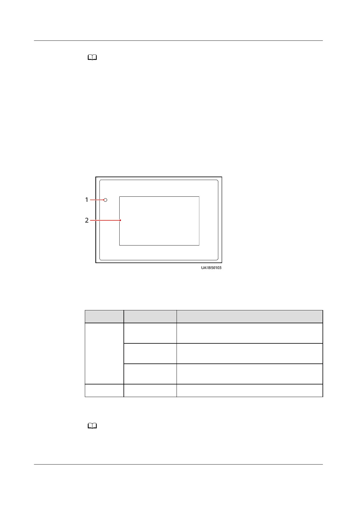
Appearance
Figure 2-20 MDU
(1) Status indicator
(2) LCD touchscreen
Table 2-11 Indicator status
Status
Color Description
On Red A critical alarm has been generated, and the
buzzer sounds continuously.
Yellow A minor alarm has been generated, and the
buzzer buzzes intermittently at 2 Hz.
Green The UPS is running properly or a warning has
been generated.
O - The MDU is powered o.
The indicator on the MDU panel is yellow when the bypass supplies power in non-ECO
mode.
UPS5000-E-(30 kVA–180 kVA)
User Manual (Integrated UPS) 2 Product Overview
Issue 02 (2022-12-30) Copyright © Huawei Digital Power Technologies Co., Ltd. 44