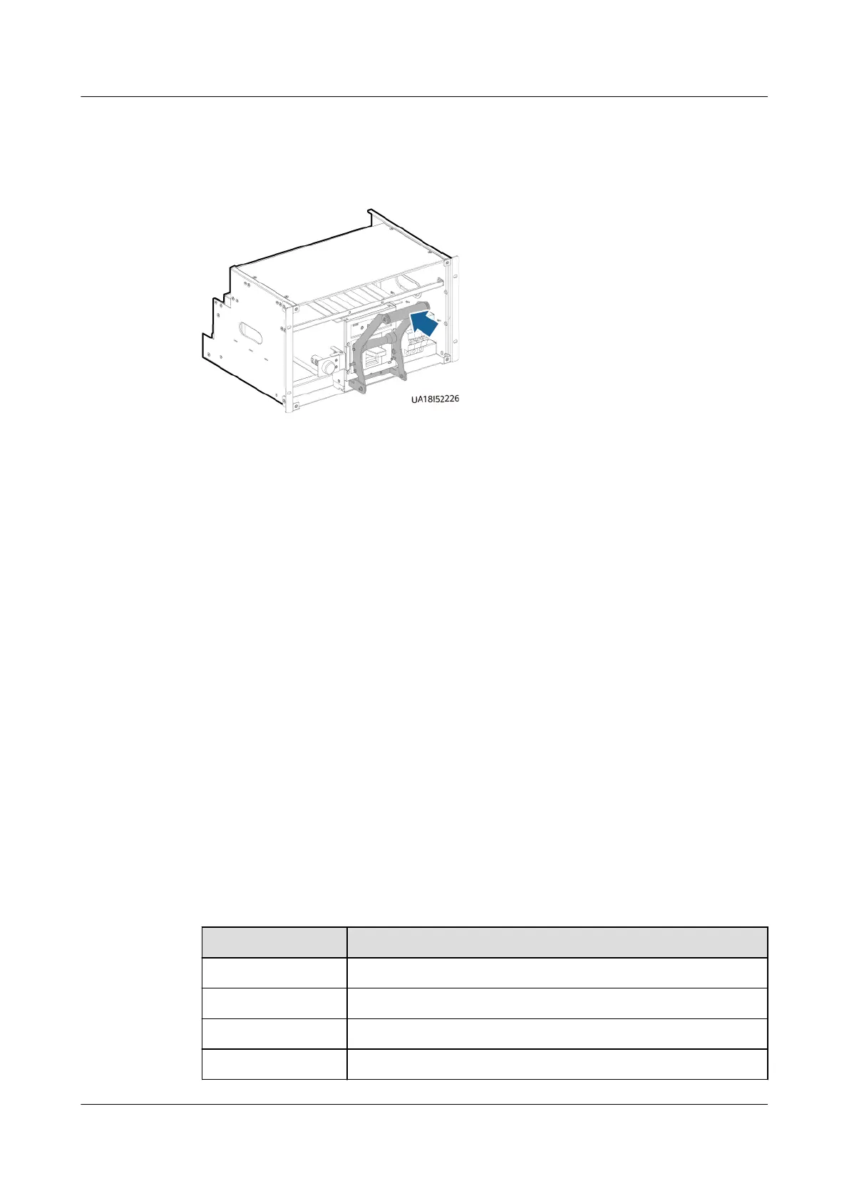
Step 13 Place the assisting tool against the switch, hold the handle of the tool, and push
the switch in place.
Figure 8-11 Pushing the switch
Step 14 Slide the assisting tool horizontally and remove it.
Step 15 Remove the fastener at the bottom of the switch and tighten the two screws you
have removed.
Step 16 Reinstall the clamping plate on t the top of the switch.
Step 17 Reinstall the front cover of the switch.
Step 18 Set the switch to the initial state.
----End
8.2 Replacing a Fuse
Prerequisites
A spare fuse of the same model is available and functional.
Context
The fuse is located in the right door panel at the rear of the cabinet.
Fuse function description:
Table 8-1 Fuses for models with MCCB input
Fuse No.
Description
FU1 Mains input L3 indicator fuse
FU2 Reserved
FU3/4/5 Mains input L1/L2/L3 fuse
FU6/7/8 UPS output U/V/W fuse
UPS5000-E-(30 kVA–180 kVA)
User Manual (Integrated UPS) 8 Parts Replacement
Issue 02 (2022-12-30) Copyright © Huawei Digital Power Technologies Co., Ltd. 161