UPS5000-E-(50 kVA-300 kVA)
User Manual (50 kVA Power Modules)
Copyright © Huawei Technologies Co., Ltd.
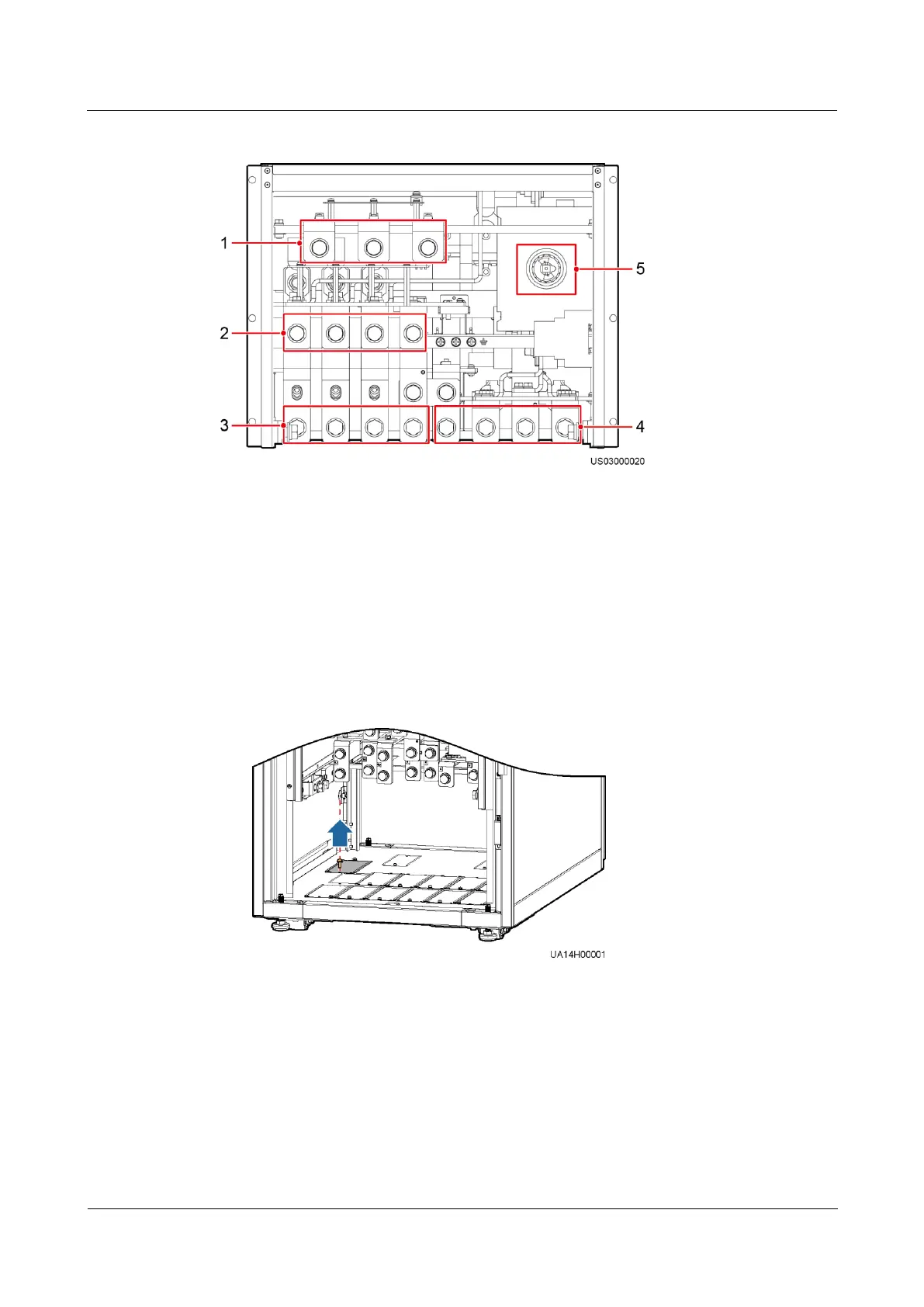
Figure 3-72 Copper bar positions
(1) Battery input terminals
(+, N, –)
(2) Bypass input terminals
(2L1–2L3, N)
(3) Mains input terminals
(1L1–1L3, N)
(4) Output terminals (U, V,
W, and N)
(5) Maintenance bypass
switch
Step 2 Determine the cabling mode.
Remove small covers for routing cables.
Figure 3-73 Removing small covers from the bottom of the cabinet
Drill holes into the large cover for routing cables.
a. Remove all small covers from the bottom of the cabinet.
b. Remove the two large covers from the top of the cabinet, drill holes into them, and
install them to the positions where the small covers were originally.