UPS5000-E-(50 kVA-300 kVA)
User Manual (50 kVA Power Modules)
Copyright © Huawei Technologies Co., Ltd.
3.2.3.3 Connecting an Ambient T/H Sensor
Procedure
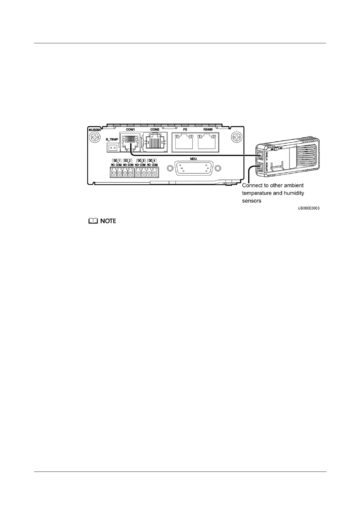
Step 1 Connect the RJ11 port on the ambient T/H sensor to the COM1 port on the monitoring
interface card.
Figure 3-20 Connecting a UPS and an ambient T/H sensor
The ambient T/H sensor can be used as a battery temperature sensor.
----End
3.2.3.4 Connecting the BCB box
Open the cover on the BCB box, and connect the BCB ports on the dry contact card to the
control signal ports on the BCB box. For details, see the PDC-(0250, 0400, 0630)
DC0384BXA BCB Box User Manual or PDU8000-(0125, 0250, 0400, 0630, 0800)
DCV8-BXA001 BCB Box User Manual.
3.2.3.5 Connecting the BBB Box
Connect the BBB box. For details, see the PDU8000-(0630, 1250, 2000) DCV8-BGA001 BBB
Box User Manual.
3.2.3.6 Installing a Battery Grounding Failure Detector
Procedure
Step 1 Install a battery grounding failure detector. For the installation method, see UPS5000 Battery
Grounding Failure Detector User Manual.