30/ENGINE ASSEMBLY 143
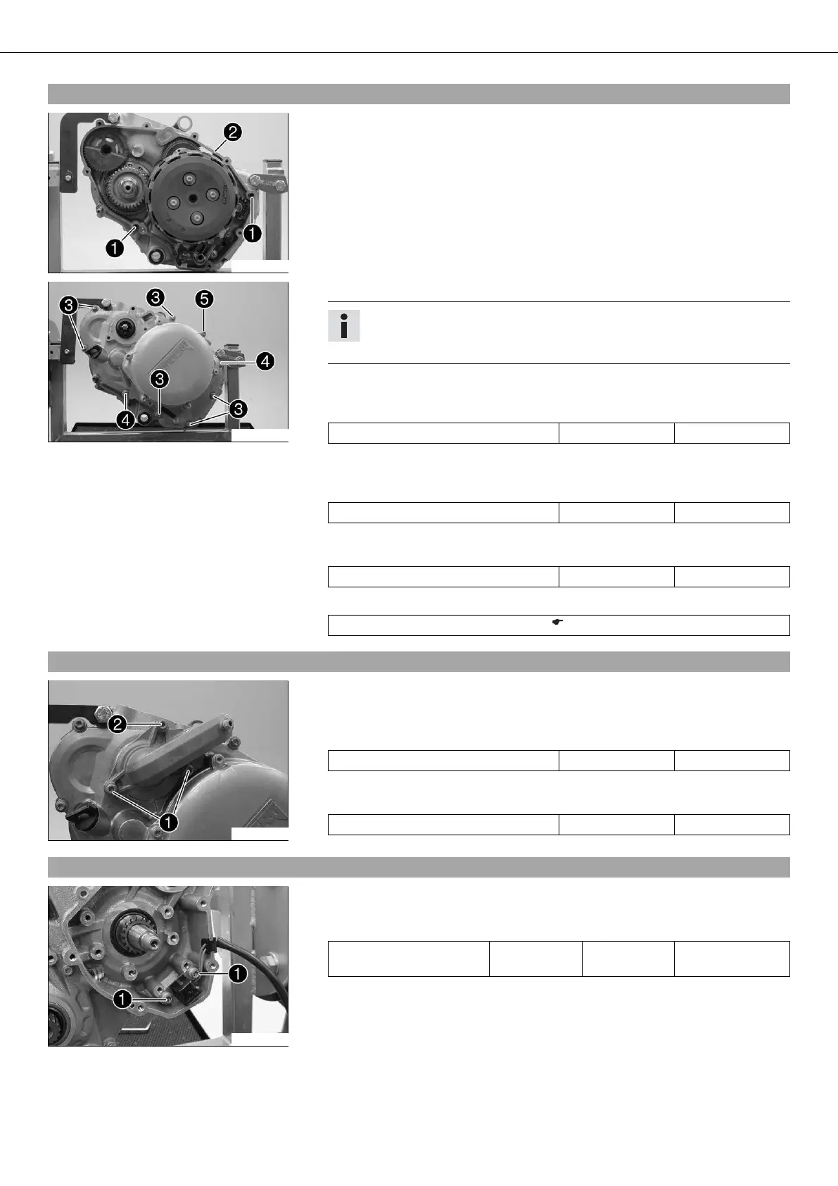
20.21Installing the clutch cover
300320-11
– Mount dowels . Put clutch cover gasket in place.
300319-11
– Mount the clutch cover.
Info
Turn the water pump impeller slightly in order to engage the water pump
drive.
– Mount screws and tighten once all of the clutch cover screws have been
mounted.
Guideline
Screw, clutch cover M6x25 10 Nm (7.4 lbf ft)
– Mount screws and tighten once all of the clutch cover screws have been
mounted.
Guideline
Screw, clutch cover M6x30 10 Nm (7.4 lbf ft)
– Mount screw and tighten all screws in a crisscross pattern.
Guideline
Screw, clutch cover M6x65 10 Nm (7.4 lbf ft)
– Position the crankshaft at top dead center (TDC) and block using the special tool.
Crankshaft locking bolt (113080802) ( p. 267)
20.22Installing the water pump cover
300318-11
– Put the water pump cover seal in place.
– Put the water pump cover on. Mount screws and tighten once all of the water
pump cover screws have been mounted.
Guideline
Screw, water pump cover M6x25 10 Nm (7.4 lbf ft)
– Mount screw and tighten all screws in a crisscross pattern.
Guideline
Screw, water pump cover M6x55 10 Nm (7.4 lbf ft)
20.23Installing the ignition pulse generator
300317-10
– Position the ignition pulse generator.
– Mount and tighten screws .
Guideline
Screw, ignition pulse gen-
erator
M5 6 Nm
(4.4 lbf ft)
Loctite
®
243™
– Position the cable and insert the cable support sleeve into the engine case.







 To Next Page