30/ENGINE ASSEMBLY 149
300518-10
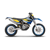
– Check the valve clearance at all valves between the valve and rocker arm.
Guideline
Valve clearance
Exhaust at: 20 °C (68 °F) 0.12… 0.17 mm (0.0047…
0.0067 in)
Intake at: 20 °C (68 °F) 0.10… 0.15 mm (0.0039…
0.0059 in)
Feeler gauge (59029041100) ( p. 269)
» If the valve clearance does not meet specifications:
– Adjust the valve clearance. ( p. 149)
300299-11
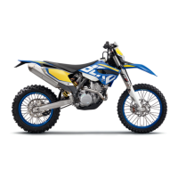
– Mount and tighten screw .
Guideline
Plug, crank shaft location with thick
copper disk
M8 10 Nm (7.4 lbf ft)
20.36Adjusting the valve clearance
– Remove the timing chain tensioner. ( p. 101)
– Remove the camshaft. ( p. 101)
300524-10
– Raise rocker arm on the outside.
– Remove shims and set down in the position in which they were installed.
– Correct the shims according to the findings from checking the valve play.
– Insert the fitting shims .
– Install the camshaft. ( p. 148)
– Install the timing chain tensioner. ( p. 148)
– Check the valve clearance. ( p. 148)
20.37Installing the generator cover
300361-10
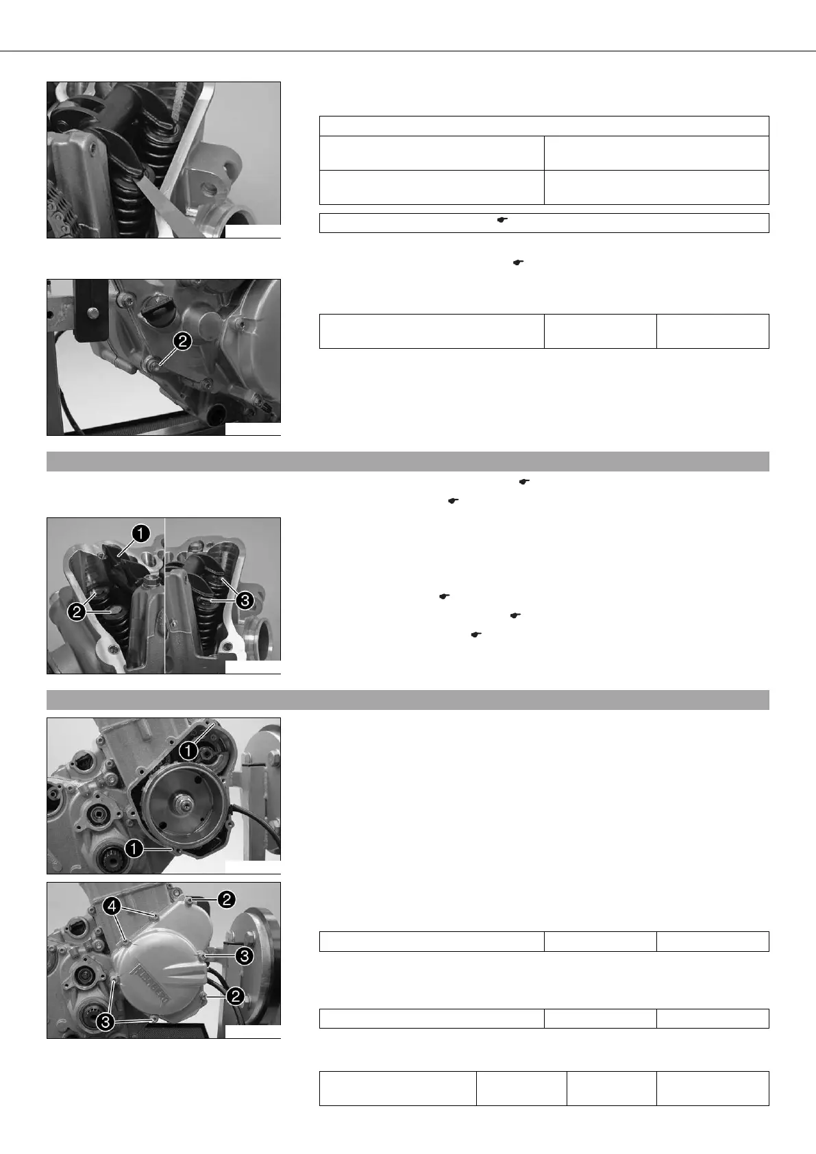
– Mount centering pins . Position the generator cover seal.
300297-12
– Position the generator cover. Mount screws and tighten once all of the generator
cover screws have been mounted.
Guideline
Screw, generator cover M6x30 10 Nm (7.4 lbf ft)
– Mount screws and tighten once all of the generator cover screws have been
mounted.
Guideline
Screw, generator cover M6x50 10 Nm (7.4 lbf ft)
– Mount screw with the seal ring and tighten all screws in a crisscross pattern.
Guideline
Screw, generator cover
(chain shaft through-hole)
M6x30 10 Nm
(7.4 lbf ft)
Loctite
®
243™
 Loading...