30/ENGINE 97
300712-10
– Position the clutch slave cylinder.
– Mount and tighten screw .
Guideline
Remaining screws, chassis M6 10 Nm (7.4 lbf ft)
– Position the shift lever.
– Mount and tighten screw .
Guideline
Screw, shift lever M6 10 Nm
(7.4 lbf ft)
Loctite
®
243™
300692-11
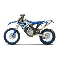
– Position the engine sprocket cover.
– Mount and tighten screws .
Guideline
Remaining screws, chassis M6 10 Nm (7.4 lbf ft)
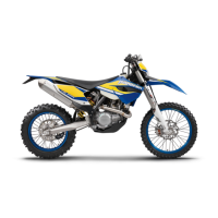
– Mount and tighten screw .
Guideline
Remaining screws, chassis M8 25 Nm
(18.4 lbf ft)
300678-12
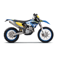
– Position the exhaust manifold.
– Mount screw but do not tighten it yet.
Guideline
Remaining screws, chassis M6 10 Nm (7.4 lbf ft)
300677-12
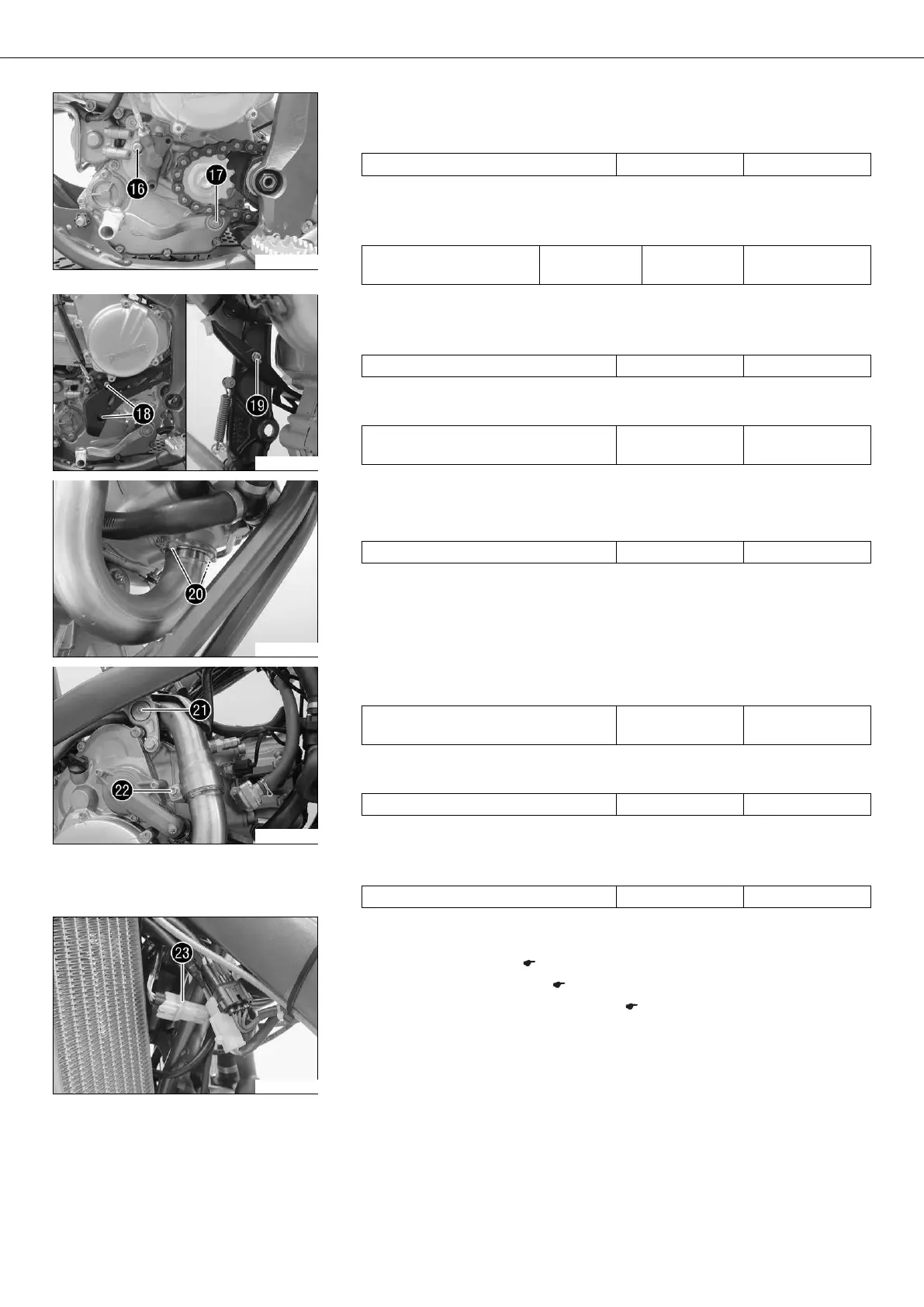
– Mount and tighten screw .
Guideline
Remaining screws, chassis M8 25 Nm
(18.4 lbf ft)
– Tighten screw .
Guideline
Remaining screws, chassis M6 10 Nm (7.4 lbf ft)
– Position the exhaust clamp.
– Tighten screw .
Guideline
Screw, exhaust clamp on manifold M8 8 Nm (5.9 lbf ft)
300676-12
– Plug in connector of the lambda sensor.
– Route the cable so it is tension-free and secure it with cable binders.
– Install the main silencer. ( p. 54)
– Install the throttle valve body. ( p. 162)
– Connect the negative cable of the battery. ( p. 73)