7. Absolute Reset and Absolute Battery
270
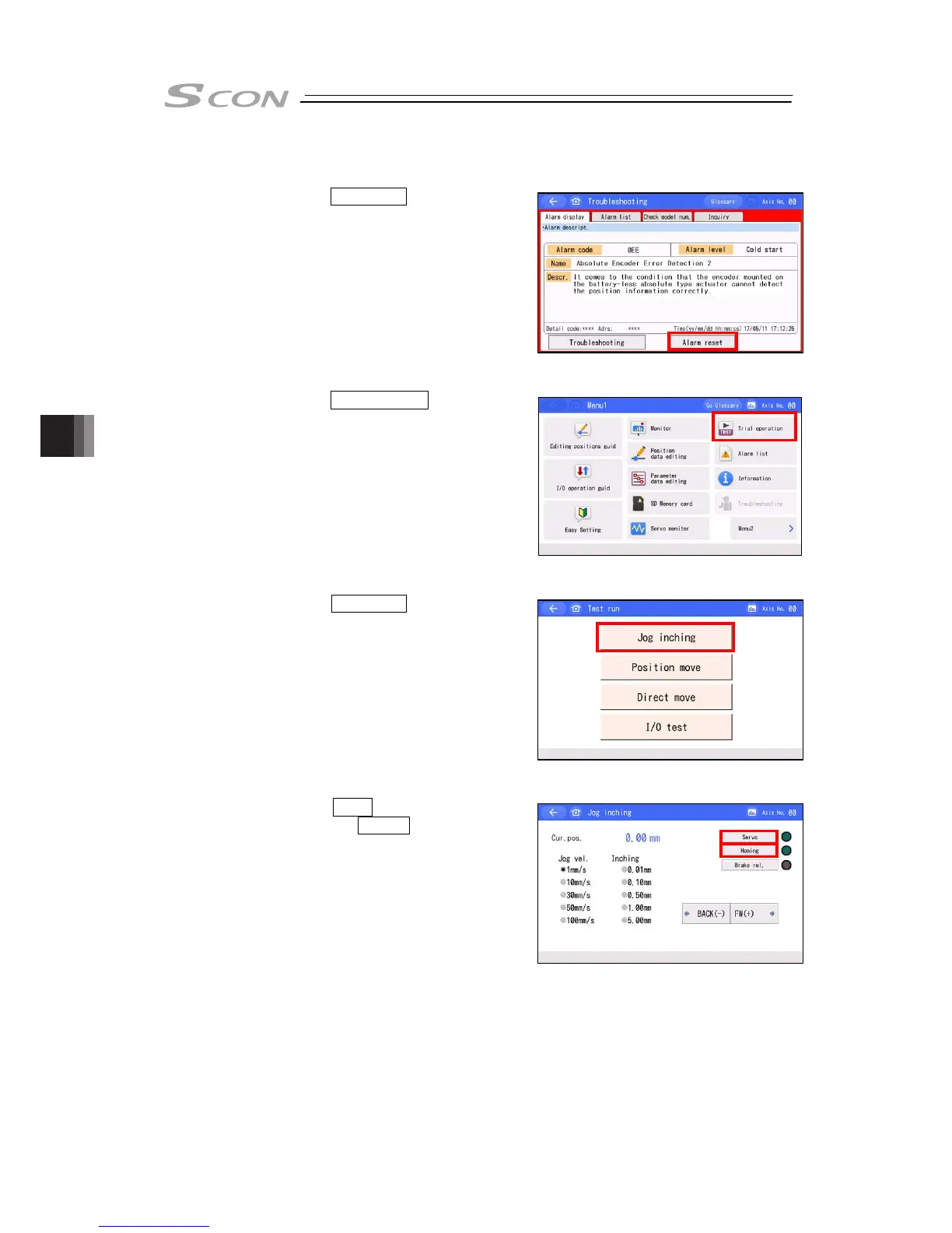
(2) For Teaching Pendant (TB-02/TB-03)
Press Alarm reset.
Press Trial Operation on the Menu
1 screen.
Press Jog inching on Test run
screen.
Touch Servo to turn the servo ON
and touch Homing in Jog inching
screen.
1
2
3
4

 Loading...


