8. Parameter
283
8.2 Detail Explanation of Parameters
Caution: • If parameters are changed, provide software reset or reconnect the power to
reflect the setting values.
• The unit (deg) is for rotary actuator and lever type gripper. Pay attention that
it is displayed in mm in the teaching tools.
[1] Zone 1+, Zone 1- (Parameter No.1, No.2)
Zone 2+, Zone 2- (Parameter No.23, No.24)
No. Name Symbol Unit Input Range
Default factory
setting
1 Zone 1+ ZNM1
mm
(deg)
-9999.99 to
9999.99
Actual stroke on +
side
2 Zone 1- ZNL1
mm
(deg)
-9999.99 to
9999.99
Actual stroke on -
side
23 Zone 2+ ZNM2
mm
(deg)
-9999.99 to
9999.99
Actual stroke on +
side
24 Zone 2- ZNL2
mm
(deg)
-9999.99 to
9999.99
Actual stroke on -
side
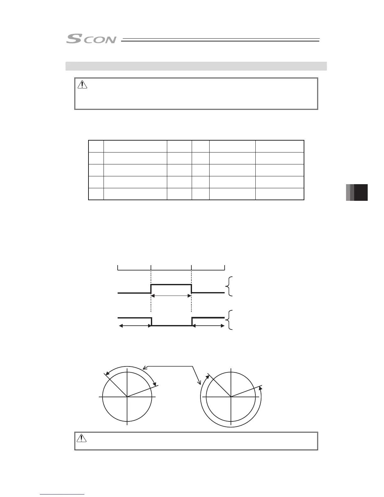
These parameters are used set the zone in which zone signal (ZONE1 or ZONE2) turns ON in
a mode other than PIO patterns 1 to 3 (ZONE2 is valid only in the pulse-train control mode).
The minimum setting unit is 0.01mm (deg).
If a specific value is set to both zone setting + and zone setting -, the zone signal is not output.
A setting sample is shown below.
[Example of when line axis]
[Example of Rotary Actuator Index Mode]
Caution: The zone detection range would not output unless the value exceeds that of
the minimum resolution (actuator lead length / No. of Encoder Pluses).
Areas that the zone
signal is ON
0°
315°
70°
0°
315°
70°
0mm 30mm 70mm
ON
ON ON
100mm
Current Position
Zone signal output
Zone signal output
Set Value
Zone setting + : 70mm
Zone setting - : 30mm
Set Value
Zone setting + : 30mm
Zone setting - : 70mm

 Loading...


