2. Wiring
127
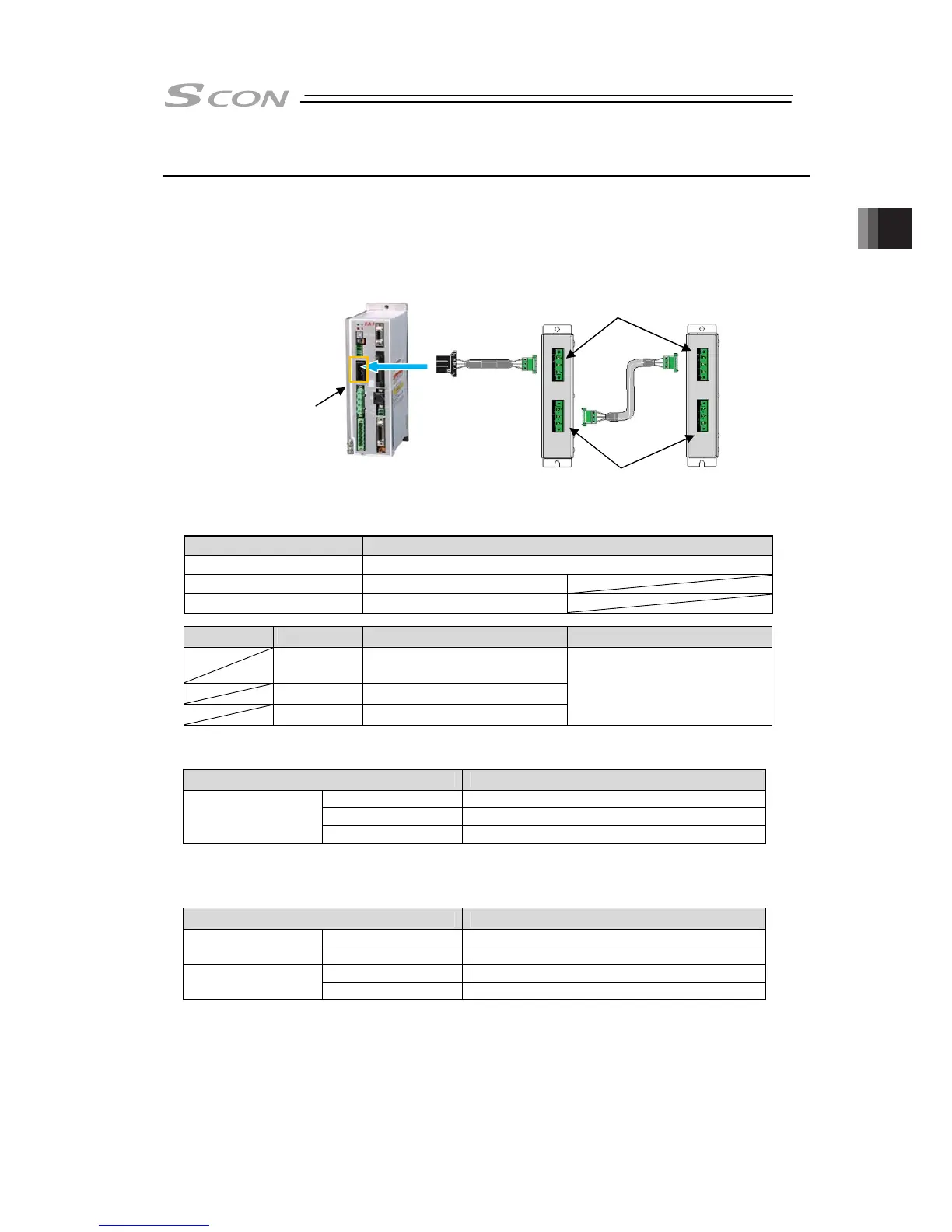
2.5.7 Connectable Regenerative Units
Connect regenerative unit (s) with attached cables as shown in the figure below.
1) When connecting 1 unit : Connect with enclosed cable (CB-SC-REU)
2) When connecting 2 or more units : Connect with enclosed cable (CB-ST-REU)
● Wiring Image
● Specification of connector for connecting external regenerative unit
Item Items and Model
Connector Name External Regenerative Unit Connector (RB)
Cable Side 1-178128-3
Controller Side 1-178138-5
Pin No.
Signal Name
Items Applicable cable diameter
RB+
Regeneration Resistor +
(Motor drive DC voltage)
RB- Regeneration Resistor -
PE Ground Terminal
Dedicated cable is enclosed
to regenerative unit
● [Reference number of connectable unit: Excluding RCS2-RA13R]
● [Reference number of connectable unit: RCS2-RA13R]
Motor Output Connectable Number of Regenerative Units
to 100W
(Note)
Not Required
101 to 400W 1
Horizontal Mount/
Vertical Mount
401 to 750W 2
(Note) One unit is necessary for LSA/LSAS-N10S Types.
Motor Output Connectable Number of Regenerative Units
Lead 1.25 Not Required
Horizontal Mount
Lead 2.5 1
Lead 1.25 1
Vertical Mount
Lead 2.5 1
RB IN
RB OUT
Regenerative Unit
Connector
1)
2)
REU-2
RESU-2
RESUD-2
REU-1
RESU-1
RESUD-1

 Loading...


