2. Wiring
100
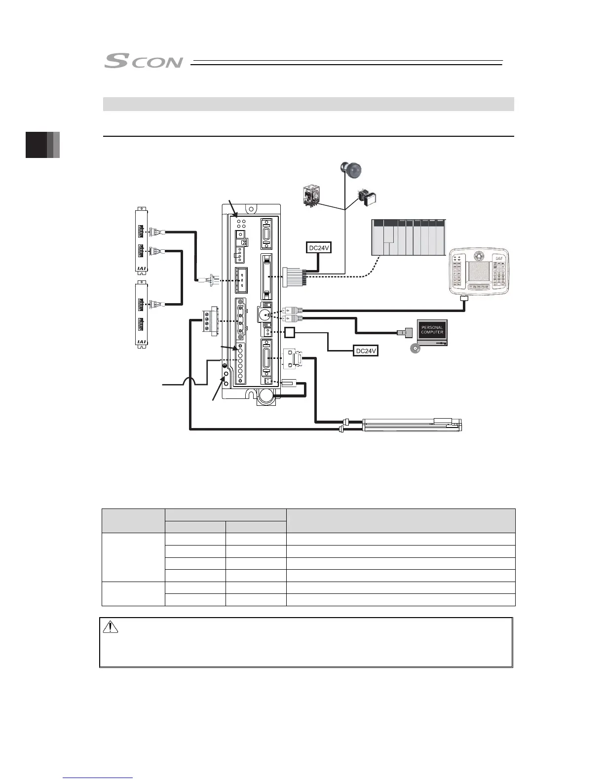
2.4 SCON-LC/LCG Type
2.4.1 Wiring Diagram (Connection of Construction Devices)
[1] Basic Wiring Diagram
Note 1 Please prepare separately.
If using RCS2-RA13R or NS Type for the actuator and the option shown in the table is applied, the
wiring between the actuator and the controller will differ from the basic wiring layout. Shown in the
table is the relation of the option and wiring layout.
○ : Equipped × : Not Equipped
Option
Model Name
Brake Loadcell
Wiring Layout between Actuator and Controller
○ × 1)
× ○ 2)
○ ○ 3)
RCS2-RA13R
× × Basic Wiring Diagram
○ - 1)
NS
× - Basic Wiring Diagram
Caution: Make sure to turn the power to the controller OFF when inserting or removing the
connector that connects the PC software or touch panel teaching.
Inserting or removing the connector while the power is turned ON causes a controller
failure.
Power Supply for Brake
It is necessary when actuator with brake
Regenerative Resistor Unit
(REU-2 : option)
Required depending
on usage condition
[Refer to 1.5.3 Regenerative Unit]
LED Display
I/O Control
Power Supply
PLC
(e.g.) Relay)
(e.g.) Lamp)
(Note 1)
Load
(Note 1)
(Note 1)
Load
(Note 1)
(e.g.) Switch)
Load
(Note 1)
CB-SC-REU010
CB-ST-REU010
Power Source
Single Phase
100V AC or
200V AC
Regenerative Resistor Unit
(REU-1 [for secondary unit] : option)
Power
Supply
Connector
Flat Cable
(Accessories)
FG Connection
Terminal
Actuator
Teaching pendant (option)
PC Software (option)
(Note1)

 Loading...


