2. Wiring
121
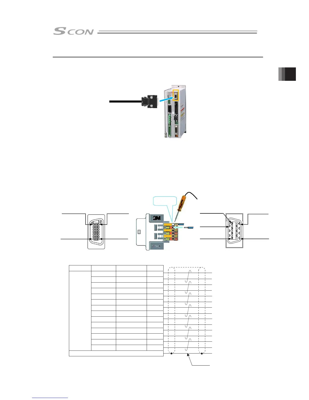
2.5.5 Pulse Train Signal Input and Feedback Pulse Output (CB/CGB Type)
Implement the wiring layout to the enclosed plug when it is necessary to read the feedback pulse
and to send the command pulse in pulse train control mode.
● Wiring Image
● Wiring Method
[1] Standard Type (Plug + Shell)
Put wires to the enclosed connector (Model code: 10114-3000PE).
See below for how to lay out the power supply wires.
1) Prepare a cable.
(Multiple twisted pair shielded cable with AWG24 (0.2mm
2
) or cable enclosed in the
connected unit (host side))
2) Solder to the connector directly.
Pay attention not to have short circuit with a terminal next to it by having pretinning and so on.
Have the cable as short as possible in order to avoid influence of noise.
1
2
3
4
―
5
―
6
PP
/PP
NP
/NP
7
/AFB
AFB
8
BFB 9
/BFB 10
ZFB 11
/ZFB 12
GND 13
0.2mm
2
(AWG24)
GND 14
Wiring Color Signal Name No.
Shield is connected to the cable clamp
Host System Side
Shield
Black
White/Black
White/Red
White/Green
White/Yellow
White/Brown
White/Blue
White/Gray
Red
Green
Yellow
Brown
Blue
Gray
Command Pulse →
Feedback Pulse ←
1
st
Pin
7
th
Pin
8
th
Pin
14
th
Pin
1
st
Pin
8
th
Pin
7
th
Pin
14
th
Pin
2
nd
Pin
Solder

 Loading...


