2. Wiring
138
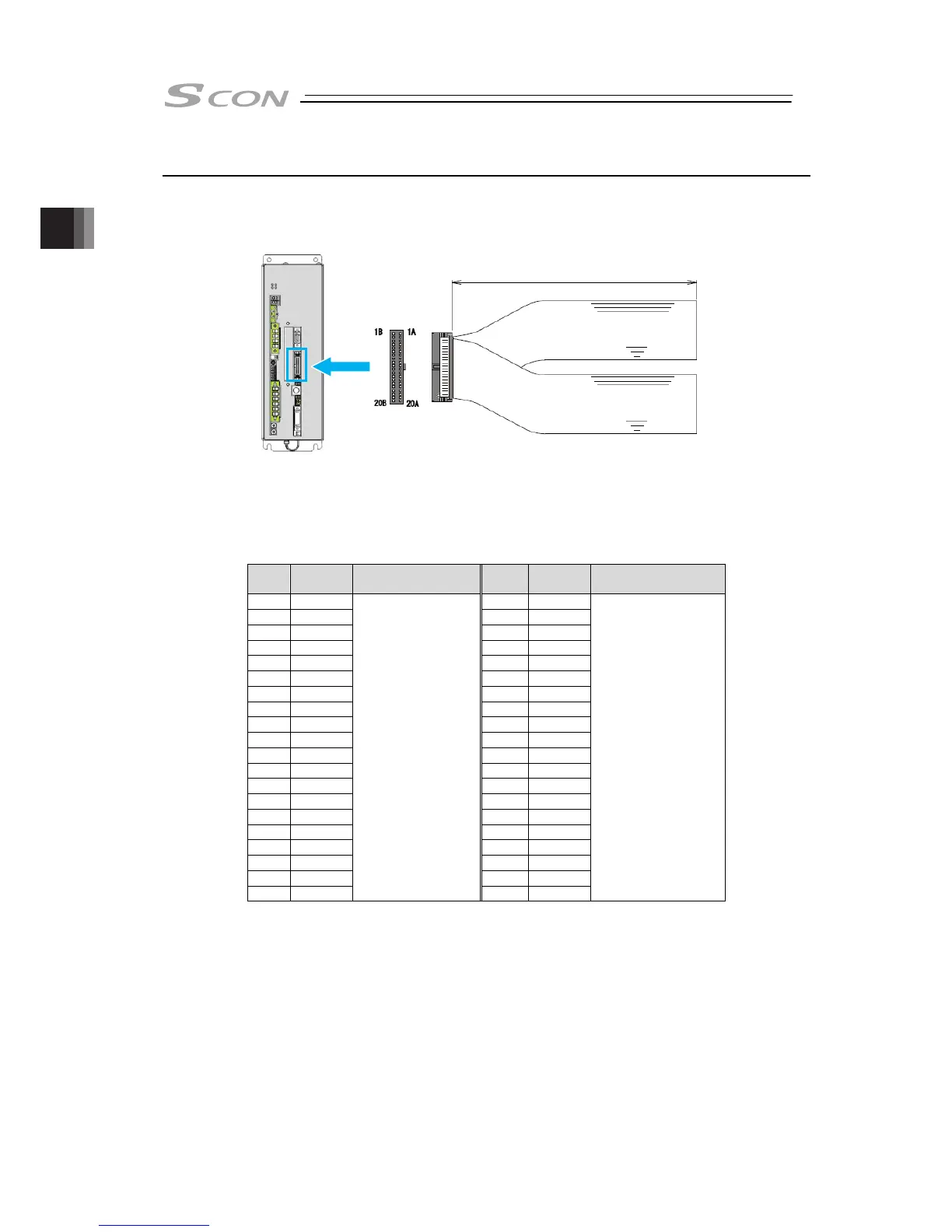
2.6.4 Connection of PIO
For the signal assignment of each wire, refer to 2.2.3 [5] PIO Circuit.
● Wiring Image
* Indicate the enclosed I/O cable length in “m” unit in the controller model code.
(5m Max.)
Up to 10m is available at maximum with separate sold option.
(Model: CB-PAC-PIO□□□: □□□ indicates the cable length L Example: 020 = 2m)
No.
Cable
Color
Wiring No.
Cable
Color
Wiring
1A BR-1 1B BR-3
2A RD-1 2B RD-3
3A OR-1 3B OR-3
4A YW-1 4B YW-3
5A GN-1 5B GN-3
6A BL-1 6B BL-3
7A PL-1 7B PL-3
8A GY-1 8B GY-3
9A WT-1 9B WT-3
10A BK-1 10B BK-3
11A BR-2 11B BR-4
12A RD-2 12B RD-4
13A OR-2 13B OR-4
14A YW-2 14B YW-4
15A GN-2 15B GN-4
16A BL-2 16B BL-4
17A PL-2 17B PL-4
18A GY-2 18B GY-4
19A WT-2 19B WT-4
20A BK-2
Flat Cable
○
A
(Press Welding)
AWG28
20B BK-4
Flat Cable
○
B
(Press Welding)
AWG28
● Wiring Method
Conduct the connection of I/O to the controller is to be carried out using the dedicated I/O cable.
Cable length is to be indicated in the controller model code. Please check the controller model
code.
A desired I/O cable can be selected from 2m (standard), 3m, and 5m cables. Up to 10m I/O
cables are sold separately.
○
A I/O output signal
○
B I/O input signal
Flat Cable (AWG28, 20cores × 2)
Half-Pitched MIL Socket
L

 Loading...


