2. Wiring
142
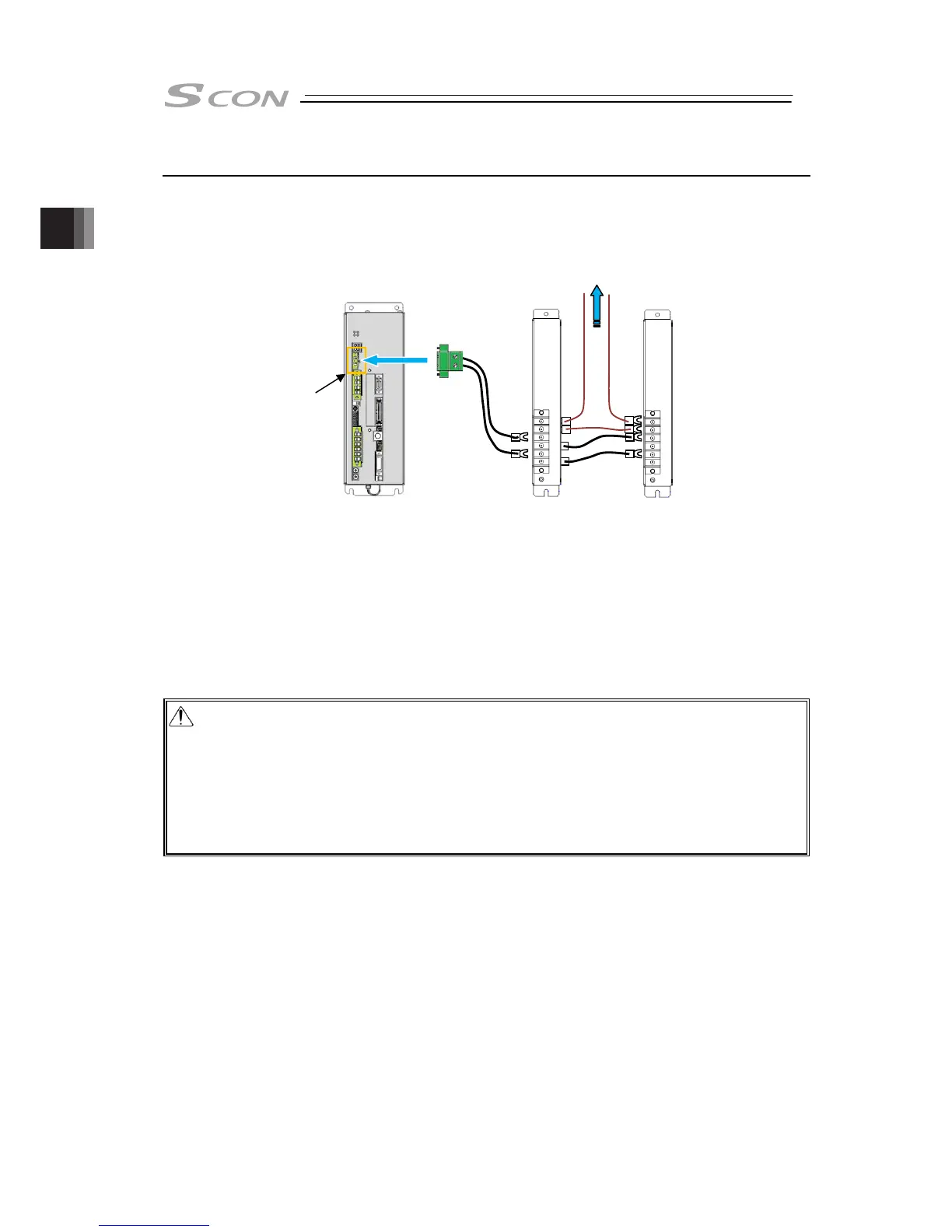
2.6.6 Connection of Regenerative Unit
Lay out necessary number of regenerative units.
● Image of wiring
● [Number of connected units]
Determine the number of regenerative units to be connected depending on the operational
conditions (payload, transfer velocity and duty ratio).
Refer to 1.3.4 Checking Duty Conveyor Type (with No Loadcell Equipped) in “ROBO Cylinder
RCS3 Rod Type Actuator Instruction Manual” (ME3742) for details.
The number of connectable regenerative units is two units at the maximum. In case “0CA”
overheat alarm gets generated even with two units connected, adjust the operational conditions
such as to make the standby duration longer or to make the velocity lower.
Caution:
1) Connecting three regenerative unit or more will cause malfunction.
2) Do not attempt to touch the regenerative units during use as the temperature gets very high.
3) Do not install them near a flammable object.
4) It is recommended to use cables with high heat resistance performance. Also, consider wire
layout so the cables would not touch the regenerative units.
5) The unit is equipped with a built-in temperature sensor. Establish the circuit constructed to cut
off the power source when the temperature sensor is in operation.
To Drive Cutoff Circuit
Temperature Sensor Contact (Contact opens
when excessive temperature rise detected)
Regenerative
Unit Connector

 Loading...


