2. Wiring
111
2.5 Wiring Method (Controller for Motors of up to 750W)
* Refer in Section 2.6 for the controller for motors of 3000W and above.
2.5.1 Wiring of Power Circuit
Power Supply Type Specifications Reference
Motor Power Supply
Control Power Supply
100V Specification : 100 to 115V AC ±10% 50/60Hz
200V Specification : 200 to 230V AC ±10% 50/60Hz
2.5.1.1 Main Power Supply Circuit (Power Supply Connector)
Supply the appropriate power from the following considering the controller type.
Loaded current may differ depending on the connected actuators. Select a circuit breaker and
leakage breaker that can apply to the specifications. [Refer to Section 1.2.3 to 1.2.4]
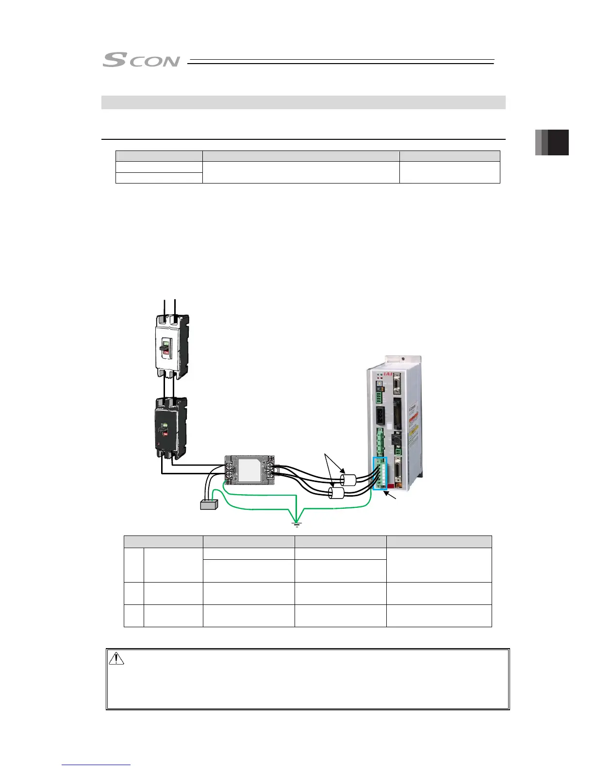
● Wiring Image
AC100 to 115V
AC200 to 230V (Note) Voltage cannot be changed after purchased.
Parts Name Model Supplier Position to attach
NAC-10-472
(Note)
COSEL
1) Noise Filter
NF2010A-UP
(Note)
SOSHIN ELECTRIC
CO.,LTD
Attach in range of
300mm or less from
controller
2) Clamp Filter ZCAT3035-1330 TDK
Attach as close as
possible to controller
3)
Surge
Protector
R • A • V-781BWZ-2A
Okaya ELECTRIC
CO.,LTD
Attach at the input
terminal of noise filter
Note It is the model code when one unit of noise filter is connected to one unit of SCON.
Caution: For the noise filter in 1), it is recommended to have one unit connected to one unit of
SCON.
* Refer also to the [reference] in the next page.
Attach 2) and 3) if necessary considering the noise environment and the power
supply condition. It is recommended to attach them even though it is not mandatory.
Circuit Breaker
(please prepare
separately
)
Leakage Breaker
(please prepare
separately
)
Noise Filter
(
please prepare separately)
Surge Protector
(
please prepare
separately
)
Power Supply
Connector
Clamp
Filter
(please
prepare
separately
)

 Loading...


