4. Field Network
256
4.2.3 Specifications
RCON Connection Type Interface Specifications
Item Contents
Number of Controlled Axes
Max. 16 Axes
* Total number of connection including A/P/D Drivers
Connector
PC Board Side : S20B-PUDSS-1 (JST)
Cable Side : PUDP-20V-S (JST)
Cable Length
Total Cable Length: 10m Max.
Length of Cables between Devices: 3m Max.
Cycle Time 1.0 / 2.0 / 3.0 / 4.0 ms
Power Voltage (Physical Layer) 24V ±10%
Input Current (Physical Layer) About 80mA
Driver Control Communication
Communication System Total Frame System
Baud Rate 3.0Mbps
Transmitted Bytes Max. 1024 bytes (64 bytes × 16 Axes)
Tool Communication
Communication System Modbus System
Baud Rate 3.0 Mbps
Transmitted Bytes 256 bytes
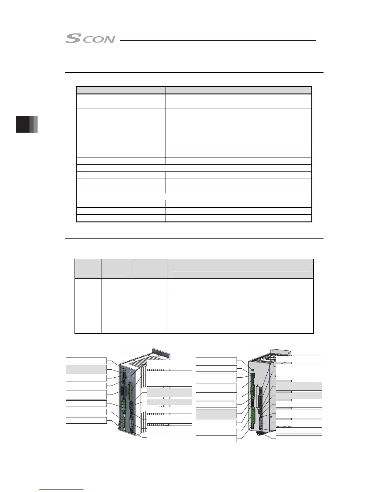
4.2.4 Name for Each Parts and Their Functions
The interface is basically the same as normal SCON products. However, following switches and
connectors should be inactivated due to the specifications of the product.
~ 750W Type 3000W ~ Type
~ 750W
Type
3000W ~
Type
Inactivated
Switch /
Connector
Restrictions
7) 4)
Axis Number
Setting Switch
The number of axes should be set in RCON gateway unit.
11) 13)
Operation Mode
Setting Switch
The operation mode should be switched over on the
operation mode setting switch in RCON gateway unit.
12) 14)
SIO Connector
A teaching tool should be connected via SIO connector on
RCON gateway unit. TP adapter (RCB-LB-TGS) should also
be connected to the gateway unit.
10) Status Indicator LEDs
9)
Charge Status Display LED
8)
Internal Regenerative
Resistor Valid Connector
7) Regenerative Unit
Connector
6) Motor Connector
5) Piano Switch
4) Axis No. Setting Switch
(Inactivated)
3) System I/O Connector
2)
Power Supply Connector
1)
FG Connection Terminal
18)
Absolute Battery Connector
19) Absolute Battery
17) Encoder Connector
16) Brake Power Supply
Connector
15) Brake Release Switch
14)
SIO Connector (Inactivated)
13) Operation Mode Setting
Switch (Inactivated)
12)
Communication Connector
for RCON
Upper End : OUT
Lower End : IN
11) Multi-Function Connector
8) Status Indicator LEDs
7) Axis Number Setting
Switch (Inactivated)
6) Piano Switch
5) System I/O Connector
4) Regeneration Unit
Connecting Connector
3) Motor Connector
2)
Power Supply Connector
1)
FG Connection Terminal
15) Encoder Connector
16) Absolute Battery
Connector
14) Brake Power Supply
Connector
13) Brake Release Switch
12)
SIO Connector (Inactivated)
11) Operation Mode Setting
Switch (Inactivated)
10)
Communication Connector
for RCON
Upper End : OUT
Lower End : IN
9) Multi-function connector
(Special Order Required)

 Loading...


