© Copyright IBM Corp. 2011 Chapter 10. Spanning Tree Protocols 121
Per-VLAN Spanning Tree Groups
PVRST mode supports a maximum of 128 STGs, with each STG acting as an
independent, simultaneous instance of STP.
Multiple STGs provide multiple data paths which can be used for load-balancing and
redundancy. To enable load balancing between two G8000s using multiple STGs,
configure each path with a different VLAN and then assign each VLAN to a separate
STG. Since each STG is independent, they each send their own IEEE 802.1Q
tagged Bridge Protocol Data Units (BPDUs).
Each STG behaves as a bridge group and forms a loop-free topology. The default
STG 1 may contain multiple VLANs (typically until they can be assigned to another
STG). STGs 2-128 may contain only one VLAN each.
Using Multiple STGs to Eliminate False Loops
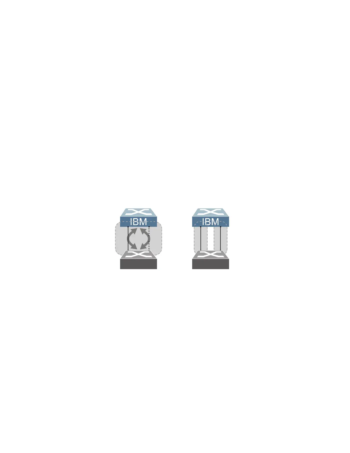
Figure 12 shows a simple example of why multiple STGs are needed. In the figure,
two ports on a G8000 are connected to two ports on an application switch. Each of
the links is configured for a different VLAN, preventing a network loop. However, in
the first network, since a single instance of Spanning Tree is running on all the ports
of the G8000, a physical loop is assumed to exist, and one of the VLANs is blocked,
impacting connectivity even though no actual loop exists.
Figure 12. Using Multiple Instances of Spanning Tree Group
In the second network, the problem of improper link blocking is resolved when the
VLANs are placed into different Spanning Tree Groups (STGs). Since each STG
has its own independent instance of Spanning Tree, each STG is responsible only
for the loops within its own VLAN. This eliminates the false loop, and allows both
VLANs to forward packets between the switches at the same time.
VLANs and STG Assignment
In PVRST mode, up to 128 STGs are supported. Ports cannot be added directly to
an STG. Instead, ports must be added as members of a VLAN, and the VLAN must
then be assigned to the STG.
STG 1 is the default STG. Although VLANs can be added to or deleted from default
STG 1, the STG itself cannot be deleted from the system. By default, STG 1 is
enabled and includes VLAN 1, which by default includes all switch ports.
VLAN 1
VLAN 30
Application Switch
Switch 1
False
Loop
Application Switch
Switch 2
VLAN 1
is active
STG 1
VLAN 30
is active
STG 2
x
With a single Spanning Tree,
one link becomes blocked.
Using multiple STGs,
both links may be active.