© Copyright IBM Corp. 2011 Chapter 21. Border Gateway Protocol 253
BGP Failover Configuration
Use the following example to create redundant default gateways for a G8000 at a
Web Host/ISP site, eliminating the possibility, if one gateway goes down, that
requests will be forwarded to an upstream router unknown to the switch.
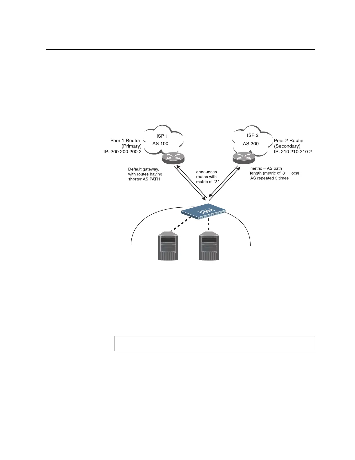
As shown in Figure 24, the switch is connected to ISP 1 and ISP 2. The customer
negotiates with both ISPs to allow the switch to use their peer routers as default
gateways. The ISP peer routers will then need to announce themselves as default
gateways to the G8000.
Figure 24. BGP Failover Configuration Example
On the G8000, one peer router (the secondary one) is configured with a longer AS
path than the other, so that the peer with the shorter AS path will be seen by the
switch as the primary default gateway. ISP 2, the secondary peer, is configured with
a metric of “3,” thereby appearing to the switch to be three router hops away.
1. Define the VLANs.
For simplicity, both default gateways are configured in the same VLAN in this
example. The gateways could be in the same VLAN or different VLANs
.
>> # vlan 1
>> (config-vlan)# member <port number>
BladeCenter
Switch
Server 1
IP: 200.200.200.10
Server 2
IP: 200.200.200.11
IP: 200.200.200.1
IP: 210.210.210.1