Job File Faults and Warnings 6-30
ICE Vulcan Service Manual
Illustrated parts list
The Illustrated Part List (IPL) contains the illustrations and the parts lists
for the different
assemblies in the system. The parts lists give the part
numbers, description and quantity of all the
items and the modules in the
printer. You can order the items and the modules for which the part
numbers are given.
How to Read the IPL
This section describes how the higher assemblies are broken down to their
related sub assemblies
and other separate parts.
Illustrations
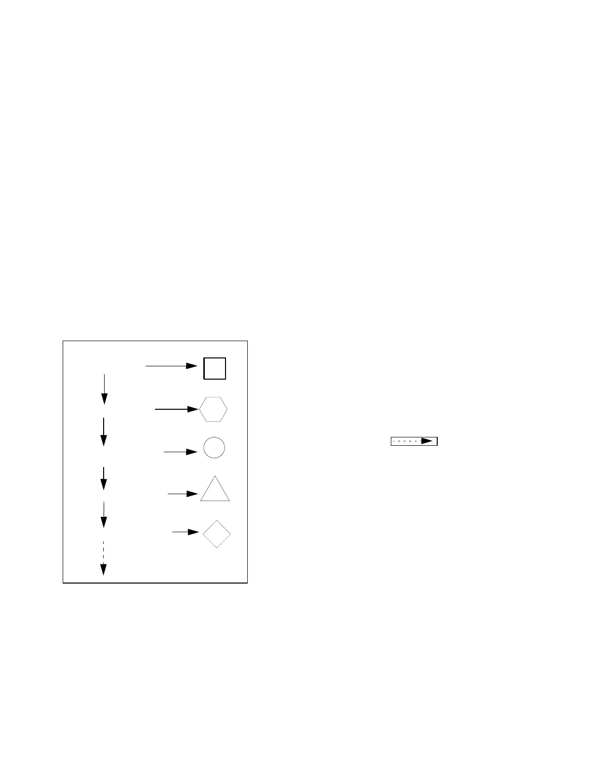
Table 7-1 on page 7-1 shows the symbols used to indicate the different
levels of main assemblies
in a system, and the sub assemblies under the
main assembly.
Main Assembly
Sub Assembly 1
Sub Assembly 2
Sub Assembly 3
Further explosion
Sub Assembly 4
Table 7-1: Symbols Representation - Assemblies
Alphabets
•
An alphabet is assigned to the main assemblies of a system and each
sub assembly
under the main assembly. See Figure 7-1.
For example: If A, B, C and D identify the main assemblies of a
system, then the alphabets E, F,
and so on identify sub assemblies
below each main assembly in a sequence.
•
The alphabets assigned to main assemblies are used only for one time.