1
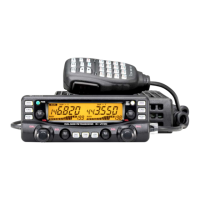
PANEL DESCRIPTION
3
q SUB BAND ACCESS INDICATORS (p. 22)
Appear when the sub band access function is activated
and indicate the function control band via the microphone
and some front panel switches (except transmitting).
w MAIN BAND INDICATORS (p. 15)
Indicate the main band for transmit and function control.
e TRANSMIT INDICATORS (p. 25)
➥ Appear while transmitting.
➥ Flash while transmitting with the one-touch PTT func-
tion (p. 26).
r FREQUENCY READOUTS
Show the operating frequency, set mode contents, etc.
• The decimal point of the frequency flashes while scanning.
(p. 42)
•“d” appears in place of the 100 MHz while the DTMF memory
function is in use; when optional units are installed, “P, ” or “C”
appears in place of the 100 MHz while the pager or code
squelch functions are in use, respectively. (pgs. 49, 59, 61)
t DUPLEX INDICATORS (p. 27)
“DUP–” or “DUP” appear during semi-duplex operation (re-
peater operation).
y TONE INDICATORS
➥ “T” appears while the subaudible tone encoder is in
use. (p. 27)
➥ “T SQL” appears while the optional tone squelch func-
tion is in use. (p. 54)
➥ “T SQLS” appears while the optional pocket beep
function is in use. (p. 53)
 Loading...