19
CONTROL COMMAND
19-7
Remote control (CI-V) information (Continued)
Cmd. Sub cmd. Data Description
1A* 05 0193 00/01 Send/read the MF band attenuator setting
(00=OFF, 01=ON)
0194 00 to 02 Send/read on-screen keyboard layout
(00=English, 01=German, 02=French)
0195 0000 to
0255
Send/read the Transmit voice level for the
VOICE TX function
(0000=0% to 0255=100%)
0196
p. 19-8 Send/read SSB-D TX bandwidth
0197 00/01
Inhibit Timer at USB connection
(00=OFF, 01=ON)
06 p. 19-9 Send/read DATA mode setting
07 00 to 01 Send/read IP+ function setting
(00=OFF, 01=ON)
1B* 00 p. 19-11 Send/read repeater tone frequency
01 p. 19-11 Set/read TSQL tone frequency
1C 00* 00 Send/read transceiver’s status RX
• When CI-V Output (for ANT) (Command:
1A 05 0157) is set to ON, automatically
outputs when changed.
01 Send/read transceiver’s status TX
• When CI-V Output (for ANT) (Command:
1A 05 0157) is set to ON, automatically
outputs when changed.
01* 00 to 02 00=Send/read the antenna tuner OFF
01=Send/read the antenna tuner ON
02=Send/read to tuning
02* 00/01 Send/read transmit frequency monitor setting
(00=OFF, 01=ON)
03 p. 19-8 Read transmit frequency
• When CI-V Output (for ANT) (Command:
1A 05 0157) is set to ON, automatically
outputs when changed.
04* 00/01 Send/read command to disable to output the
antenna controller status frequency and so on
from [REMOTE]
• Send/read command to enable to output the
antenna controller status frequency and so
on from [REMOTE].
1E 00 Read number of available TX frequency band
01 p. 19-8 Read TX band edge frequencies
02 Read number of user-set TX frequency band
03* p. 19-8
Send/read user-set TX band edge frequencies
21* 00 p. 19-11 Send/read RIT frequency
01 00/01 Send/read RIT setting (00=OFF, 01=ON)
02 00/01
Send/read ∂TX setting (00=OFF, 01=ON)
25* p. 19-11 Send/read the selected or unselected VFO
frequency
26* p. 19-11 Send/read the selected or unselected VFO’s
operating mode and lter
27* 00 p. 19-12 Read the Scope waveform data
• Only when “Scope ON/OFF status”
(Command: 27 10) and “Scope data output”
(Command: 27 20) are set to “ON,” outputs
the waveform data to the controller.
10 00/01 Send/read the Scope ON/OFF status
(00=OFF, 01=ON)
11 00/01 Send/read the Scope wave data output*4
(00=OFF, 01=ON)
12 00 Send/read the Main or Sub scope setting
(00=Main only)
13 00 Send/read the Single/Dual scope setting
(00=Single only)
14 p. 19-12 Send/read the Scope Center mode or Fixed
mode setting
15 p. 19-12 Send/read the span setting in the Center
mode Scope
16 p. 19-12 Send/read the Edge number setting in the
Fixed mode Scope
17 p. 19-12
Send/read the Scope hold function ON or OFF
19 p. 19-12 Send/read the Scope Reference level setting
1A p. 19-13 Send/read the Sweep speed setting
1B 00/01 Send/read the Scope indication during TX in
the Center mode (00=OFF, 01=ON)
D Command table (Continued)
* (Asterisk) Send/read data
*1 To insert a counter, rst clear the other channel’s counter.
*2 In the CW mode, if the [TRANSMIT] or an external TX
switch is ON, or the Break-in function is ON, a message
will be transmitted as CW code when you send it from
your PC.
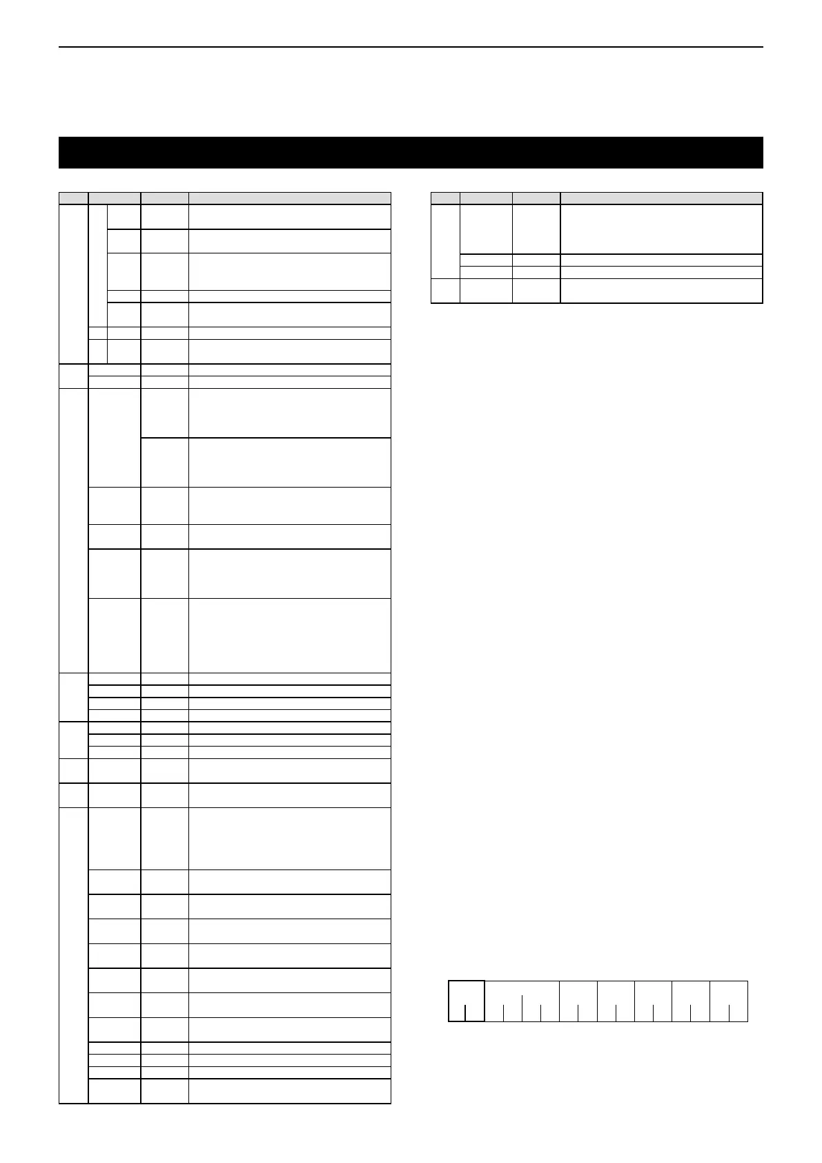
*3 When sending the power ON command (18 01), you need
to repeatedly send “FE” before the standard format. The
following is the approximated quantity of the repetition.
• 115200 bps: 150 “FE”s
• 57600 bps: 75 “FE”s
• 38400 bps: 50 “FE”s
• 19200 bps: 25 “FE”s
• 9600 bps: 13 “FE”s
• 4800 bps: 7 “FE”s
Example: When using 4800 bps
F
F E
49EFE E 1081O DF
*4 You can only set this item when “Unlink from [REMOTE]”
is selected on the “CI-V USB port” screen, and then
“115200” is selected on the “CI-V Baud Rate” screen.
Cmd. Sub cmd. Data Description
27* 1C 00 to 02 Send/read scope center frequency setting in
the Center mode
( 00=Filter center, 01=Carrier point center,
02=Carrier point center (Abs. Freq.)
1D p. 19-13 Send/read the Scope VBW setting
1E p. 19-13 Send/read the Scope Fixed edge frequencies
28* 00 00 to 08 Transmits the Voice TX memory content
(00=T1 to 08=T8, 0x00=Cancel TX)