IDS Base Station Receiver 400 700-179-02B Issued January 2009 14
3.
3.3.
3.
Operation
OperationOperation
Operation
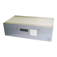
After connecting up the IDS BSR400, as described in section 2 Installation, switch on the AC mains
supply then switch on the 18V AC and battery power switch protruding though the back panel above the
18V AC input socket or beside the mains input plug on IDS BSR400 versions.
The Base Control Processor (BCP) will search for installed line cards, displaying the following example on
the 20 x 4 line LCD user status display of the IDS BSR/400 front panel:
IDS BSR
IDS Digital Receiver
Firmware Ver. 3.00
<001201.1653>
SEARCHING FOR LCx
FOUND LCx
For an active line card, OR
LCx
NOT RESPONDING
Where no line card has been detected, i.e. not installed.
IDS BSR400
IDS Digital Receiver
IDS Digital Receiver
IDS Digital Receiver
IDS Digital Receiver
FOUND LC1
FOUND LC2
LC3 NOT RESPONDING
LC4 NOT RESPONDING
This indicates the line cards detected and those not installed.
Once the BCP has established the number of line cards installed in the IDS BSR400, the current settings
relevant to each active line card will be transferred to each card. This occurs each time the IDS BSR400
unit is switched off and then on. The BCP will now be in the UN-VIEWED EVENTS state as a result of the
most recent events having been loaded into the “Event Log”. The value at the bottom of the display
indicates the number of un-viewed events.