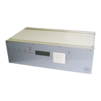
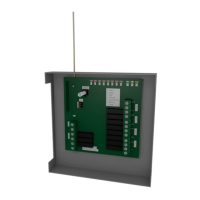
IDS Base Station Receiver 400 700-179-02B Issued January 2009 22
3.3.5
3.3.53.3.5
3.3.5
Format Option Selection
Format Option SelectionFormat Option Selection
Format Option Selection
Contact ID:
Contact ID:Contact ID:
Contact ID: There are two bit settings that change the display, print and serial data output format.
What to set these bits to will depend on what the monitoring program’s contact ID event code
settings are. They are:
• To select an alpha (default) or numeric “Qualifier” or not, see 4.3.7 Contact ID Alpha or
Numeric Qualifier and
• To convert “A
AA
A” to “0
00
0” (default) see 4.3.7 Contact ID Conversion of Zero Character.
4x2:
4x2:4x2:
4x2: This bit setting changes the display, print and serial data output format, converting “A
AA
A” to
“0
00
0”. The default is A not converted to 0, see 4.3.7 4x2 Format Conversion of Zero Character
System Messages:
System Messages:System Messages:
System Messages: There are three bit settings to enable/disable the output of system messages
to the monitoring program. These are:
• ERROR Events, see 4.3.7 Enable/Disable Outputting ERROR events
• Missed Calls, see 4.3.7 Enable/Disable Printing Missed Call
• Comms Events, see 4.3.7 Enable/Disable Outputting Comms Absent/Restoral events
3.3.6
3.3.63.3.6
3.3.6
SIA Handshake Enabled
SIA Handshake EnabledSIA Handshake Enabled
SIA Handshake Enabled
If this format is to be used make sure that it is entered in the line card handshake sequence setting
(default 2314 where 4 = SIA), see 4.7.1 Handshake Order M5x1.
3.3.7
3.3.73.3.7
3.3.7
Plain Library
Plain LibraryPlain Library
Plain Library
For ease of use when in stand alone or during PC down time it is recommended that the plain library is
enabled and setup 4.4.3 Plain Library M202.
3.3.8
3.3.83.3.8
3.3.8
General Insta
General Insta General Insta
General Installations
llationsllations
llations Management
Management Management
Management
The following is recommended where the implementation is possible:
Use formats that have pre-defined event codes, Contact ID or SIA.
Use a format that uses DTMF modulation.
Subscribe to the Telephone Communication Service Provider’s “Caller ID” service. This will assist
in identifying the source of re-occurring “Missed Call” error message, as the telephone number
will be displayed prior to the “Missed Call” error message.
When selecting and assigning event codes use the “First Digit” as an “Identifier” or “Group
Identifier” digit. This simplifies the “Plain Library” allocation. Here are some examples 1...8.
• Example 1: 4[1...F], 4 = Alarm from zone [1...F]
• Example 2: 6[1...F], 4 = Close by user 1...F
• Example 3: F [1...F], F = Burglary, zone in [1...F]
• Example 4: A [1...F] A = Alarm/Burglary [1...F] = zone
• Example 5: C [1...F] C = Close [1...F] = user or [1...F] = zone
• Example 6: 1[1...F] 1 = Fire [1...F] = user or [1...F] = zone
• Example 7: 2[1...F] 2 = Panic [1...F] = user or [1...F] = zone
• Example 8: 3[1...F] 3 = Medical [1...F] = user or [1...F] = zone
3.4
3.43.4
3.4
Testing
TestingTesting
Testing
Program an alarm panel then test its operation with the IDS BSR400 using the instructions in paragraph
5.1.7 BSR400 – Alarm Panel Communication Test.