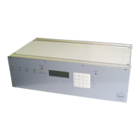
IDS Base Station Receiver 400 700-179-02B Issued January 2009 15
03 DEC 2000 16:48
UN-VIEWED EVENTS
4
Depending on the settings, the front panel buzzer and the external alarm connected to the relay output
will sound. The buzzer will stop sounding if an event is viewed or the CANCEL key is pressed. The
alarm will stop sounding when the all the events have been viewed.
3.1
3.13.1
3.1
Front Panel LED
Front Panel LEDFront Panel LED
Front Panel LED
Each IDS BSR400 plugin card has one or two LED’s, which indicate the status of the card and system.
The action and status of each LED is described below.
3.1.1
3.1.13.1.1
3.1.1
AC Supply LED
AC Supply LEDAC Supply LED
AC Supply LED
The “Green” LED on the power supply card (right of the keypad) indicates the mains supplied 18V AC is
on. If you switch the mains off at the socket the “Green” LED will turn off but the LCD, displaying the
information as shown above, should remain on indicating that the 12V battery is connected.
3.1.2
3.1.23.1.2
3.1.2
Trouble LED
Trouble LEDTrouble LED
Trouble LED
The “Red” LED on the control card (first set of LED’s on the left of the LCD) indicates a “Trouble” system
condition has been detected (see Table 2: TROUBLE Conditions) which needs to be corrected. Press the
7 key to access the “Trouble Display” then 5 or 6 key to scroll through if there is more than
one trouble event.
3.1.3
3.1.33.1.3
3.1.3
Event LED
Event LEDEvent LED
Event LED
The “Yellow” LED on the control card (first set of LED’s on the left of the LCD) indicates that an alarm
event has been received which has not been viewed.
3.1.4
3.1.43.1.4
3.1.4
Line Card LED
Line Card LEDLine Card LED
Line Card LED
The remaining one to four “Green” LED’s, depending on the number of cards installed, are on the line
cards and indicate their state. A low rate pulsing green LED indicates the line card is scanning the
telephone line for an incoming call. A static greed LED indicates the line card has detected an incoming
call and is in the process of handshaking and reading in the event record or outputting the kiss off
handshake to indicate the end of the input process.
On the IDS BSR400 or if the line card software has been upgraded to version 2.00 or higher the line card
will not issue a kiss off until the control card has read the received event. If the control card fails to read
the event the line card will pulse the LED at a twice the normal rate to indicate a fault condition. In the
event that this occurs the line card will not respond to any other panel events to force the panels to
communicate on another line preventing any lost events.
3.2
3.23.2
3.2
Keypad
KeypadKeypad
Keypad
The IDS BSR400 has a 16 key alphanumeric key pad. The keypad is normally in the numeric mode, 0 to
9, and where necessary it is switched to the alpha mode to enter A to Z and a to z. The keypad functions
are as follows: