IDS Base Station Receiver 400 700-179-02B Issued January 2009 73
8.
8.8.
8.
Appendix D
Appendix DAppendix D
Appendix D
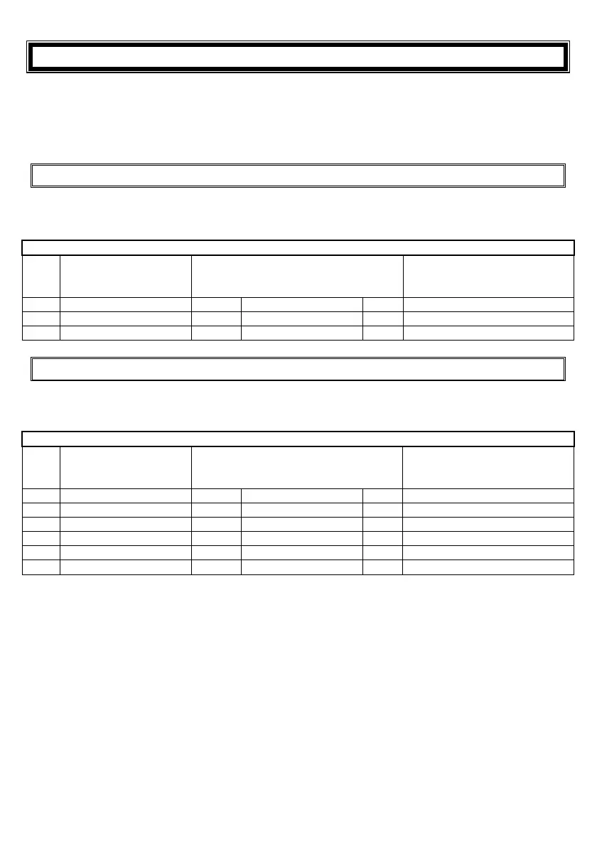
The following are the connections for the serial cable between the IDS BSR/400 RS232 PC (Sout) port
and the PC Monitoring program and IDS BSR/400 RS232 IN port (Sin) for the Base (Sout) to Base (Sin)
facility or output printer formatted events to a terminal emulator (Hyper Terminal) on the PC. The cable
supplied with the IDS BSR/400 has a 25 Way, table above, and a 9 Way, table below, connector to
facilitate connecting to either type of D Type Female serial connector provided by the PC.
8.1
8.18.1
8.1
IDS BSR400 RS232 PC (Sout) to the PC’s 25
IDS BSR400 RS232 PC (Sout) to the PC’s 25IDS BSR400 RS232 PC (Sout) to the PC’s 25
IDS BSR400 RS232 PC (Sout) to the PC’s 25
Way Connector
Way ConnectorWay Connector
Way Connector
The following are the connections for the serial cable between the IDS BSR/400 and a PC with a 25 Way
D type connector.
Device Connector Description
Device Connector DescriptionDevice Connector Description
Device Connector Description
25 PIN D-SUB FEMALE
connector plugged in
to the PC’s COMx Port
Connection
25 PIN D-SUB MALE connector
plugged in to the BSR400’s
RS232
RS232RS232
RS232
PC
PC PC
PC connector (Sout
SoutSout
Sout)
Pin
PinPin
Pin
Signal Name
Signal NameSignal Name
Signal Name
Dir
DirDir
Dir
Line Description
Line DescriptionLine Description
Line Description
Pin
PinPin
Pin
Signal Name
Signal NameSignal Name
Signal Name
1 Shield
Shield Ground 1 Shield
2 TXD
Transmit Data 2 RXD1
8.2
8.28.2
8.2
IDS BSR400 RS232 PC (S
IDS BSR400 RS232 PC (SIDS BSR400 RS232 PC (S
IDS BSR400 RS232 PC (Sout) to the PC’s 9
out) to the PC’s 9out) to the PC’s 9
out) to the PC’s 9
Way Connector
Way Connector Way Connector
Way Connector
The following are the connections for the serial cable between the IDS BSR/400 and a PC with a 9 Way D
type connector.
Device Connector Description
Device Connector DescriptionDevice Connector Description
Device Connector Description
9 PIN D-SUB FEMALE
connector plugged in
to the PC’s COMx Port
This connector is connected to the 25
way FEMALE connector to
accommodate either socket
25 PIN D-SUB MALE connector
plugged in to the BSR400’s
RS232 PC
RS232 PCRS232 PC
RS232 PC connector (Sout
SoutSout
Sout)
Pin
PinPin
Pin
Signal Name
Signal NameSignal Name
Signal Name
Dir
DirDir
Dir
Signal Name
Signal NameSignal Name
Signal Name
Pin
PinPin
Pin
Signal Name
Signal NameSignal Name
Signal Name
3 TXD
Transmit Data 2 RXD1
2 RXD
Receive Data 3 TXD1
7 RTS
Not Used 4 CTS1
8 CTS
Not Used 5 RTS1
5 GND System Ground 7 GND