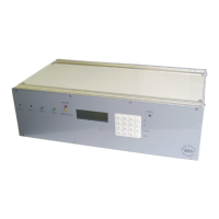
IDS Base Station Receiver 400 700-179-02B Issued January 2009 7
1.1
1.11.1
1.1
Specifications
SpecificationsSpecifications
Specifications
Design and Construction
• Facility to connect multiple receivers to a single computer
• User programmable
• 19" rack enclosure with optional rack mounting brackets
• Modular design - low down time on maintenance
• Excellent lightning protection
• IDS BSR - 32VA 16V AC supply
• IDS BSR400 – 220 Volts 50Hz AC
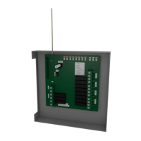
Back Plane Facilitates the following
• Power Supply, 64 pin Din Socket
• 18V AC supply and battery power on/off switch
• Base Station Control Card, 64 pin Din Sockets
• 4 Line Cards, 64 pin Din Sockets
• 4 Telephone Line Input, RJ11 Socket
• Parallel Printer Output, Pout, 25 Way D-type Socket
• Serial Output, Sout, 25 Way D type Socket to connect to “Monitoring” program
• Serial Input, Sin, 25 Way D type Plug for “Base-to-Base” communication to enable
monitoring more than one base station on a single serial port
• IDS BSR - 32VA 16V Power Supply Input
• IDS BSR400 – Kettle Plug 220 Volt AC Input
• 2 pin Phoenix Remote Alarm Relay Output, switched 12V - 500mA output.
• 3 pin Phoenix Remote Up Arrow and Cancel Key Input, IDS BSR400 only
System Self-Monitoring Facilities.
• Low battery supply detector, 11.0 to 11.5 volts for faulty battery and/or when the AC input
falls below ~ 15V with no battery connected
• AC fail detection when the AC input falls below ~ 10V
• Watch-dog timer on the PSU that will reset the system if not accessed by the control card
Base Station Control Card
• 700 non-volatile “Alarm Event Log”
• Alarm Event displayed when received and up to 255-Events viewable on the LCD
• Alarm Event output on the Sout port to the Monitoring Application on a PC when received,
and up to 699-events may be re-printed from the log
• Alarm Event printed when received and up to 699 may re-printed from the log
• Printer formatted Alarm Event output on Sin port to text input application on a PC when
received
• Up to 699 printer formatted Alarm Event may be output on Sin port to a text input application
on a PC from the log
• Non-Volatile “User Programmable” system setup settings
• Programmable buzzer and relay alarm
• Plain language message display and print capability
• Real-time clock
• Continuous verification of the line card receiver link by polling during in-active periods