IDS Base Station Receiver 400 700-179-02B Issued January 2009 56
5.1.2
5.1.25.1.2
5.1.2
DSC 4020 Alarm Panel
DSC 4020 Alarm PanelDSC 4020 Alarm Panel
DSC 4020 Alarm Panel
This panel may give an ERROR condition, see ERROR condition.. It appears that the check sum
calculation of a 0 (zero) account code digit is different. To correct this allocate an account code with no
0’s (zero).
5.1.3
5.1.35.1.3
5.1.3
Guard Master
Guard MasterGuard Master
Guard Master
See Watch Manager below.
5.1.4
5.1.45.1.4
5.1.4
Watch Manager
Watch ManagerWatch Manager
Watch Manager
When setting up to an existing installation using this monitoring program it may be necessary to alter the
Event Code output format to the monitoring program. This may occur when you replace OEM base
station with the IDS BSR400. See paragraph 4.3.7 Format Options M107.
5.1.5
5.1.55.1.5
5.1.5
Verifying Base Station Operation
Verifying Base Station OperationVerifying Base Station Operation
Verifying Base Station Operation
To check the base station operation simply power off and then after two seconds power it on again and
check that the following occurs:
NOTE:
If an event is received during this sequence, it will be displayed in between the “System” messages
shown below.
The Control Card scanning for line cards.
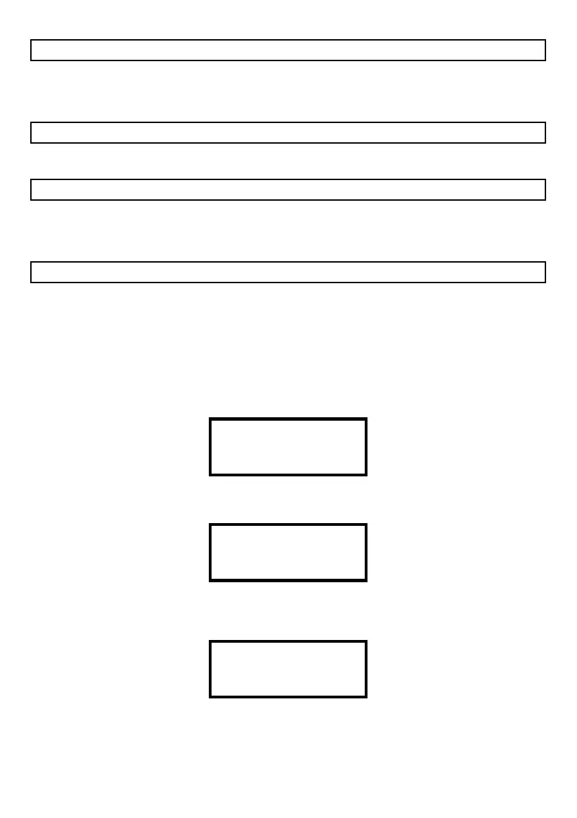
IDS Digital Receiver
IDS Digital Receiver
IDS Digital Receiver
IDS Digital Receiver
The Control Card detects the number of line cards installed.
FOUND LC1
FOUND LC2
LC3 NOT RESPONDING
LC4 NOT RESPONDING
Reporting a “System Reset” on the display:
10 APR 2007 16:48
System MSG
System Reset
4
Report the “System” message to the monitoring program if connected (no “Comms Absent”
displayed) and running.
• 1010ssssss0000sRsD0 (Power Up message)