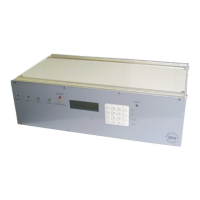
IDS Base Station Receiver 400 700-179-02B Issued January 2009 13
IDS BSR:
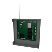
Remove the right hand side panel.
Locate and connect the red and black battery cables to the battery.
Reassemble.
2.2.4
2.2.42.2.4
2.2.4
Ground Connection
Ground ConnectionGround Connection
Ground Connection
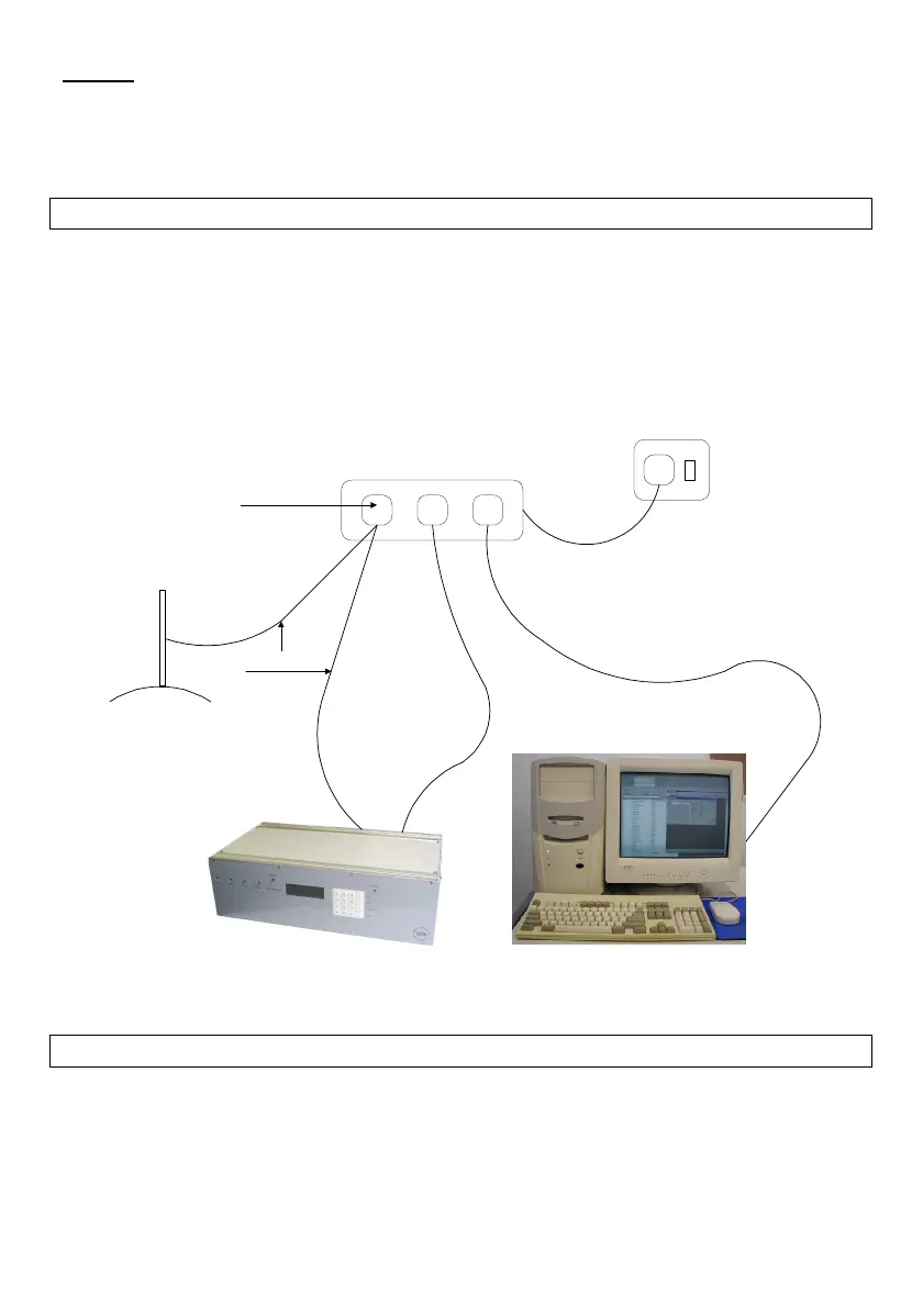
To reduce the risk of light or power surges damaging the IDS BSR400 or PC it is important to connect
them as follows:
Both units must be plugged into the same main dual wall outlet socket or via a multi socket
adapter. The lead to the multi socket adapter must be less than half a meter.
A high current capacity earth lead, where possible, must be connected from one of the multi
socket adapter socket’s earth pin to a ground spike or mesh.
IDS BSR400 with an earth terminal on the rear panel, from Mod level Axxx.xxx and higher, must
be connected to the same multi socket adapter’s socket earth pin with a high current capacity
earth lead.
Figure 5: IDS BSR400 System Grounding
2.2.5
2.2.52.2.5
2.2.5
Connecting Up
Connecting UpConnecting Up
Connecting Up
Connect up the serial (D1 and D2) and printer (P1) cables, the telephone lines (L1...4) and any remote
devices (R1 and R2) as shown above, then connect the power supply. The IDS BSR400 operates off 220
volts AC via a kettle plug cable (M) and the IDS BSR requires 16 Volt 32VA AC supply (T).
Earth spike
or mesh
Earth Lead
Connect to
Earth
Terminal