IDS Base Station Receiver 400 700-179-02B Issued January 2009 59
Above the 400 of the label IDS BSR$400 CONTROL CARD Ver D, identified as CN3.
Switch off the BSR400, hold a screwdriver across CN3 and switch on the BSR400.
When the Display shows "LOADING DEFAULTS" remove the screwdriver.
The BSR400 should now operate as normal.
NOTE:
You should get the same results described in paragraph 5.1.5 Verifying Base Station Operation above
after the reset.
5.1.7
5.1.75.1.7
5.1.7
BSR400
BSR400 BSR400
BSR400 –
––
– Alarm Panel Communication Test
Alarm Panel Communication Test Alarm Panel Communication Test
Alarm Panel Communication Test
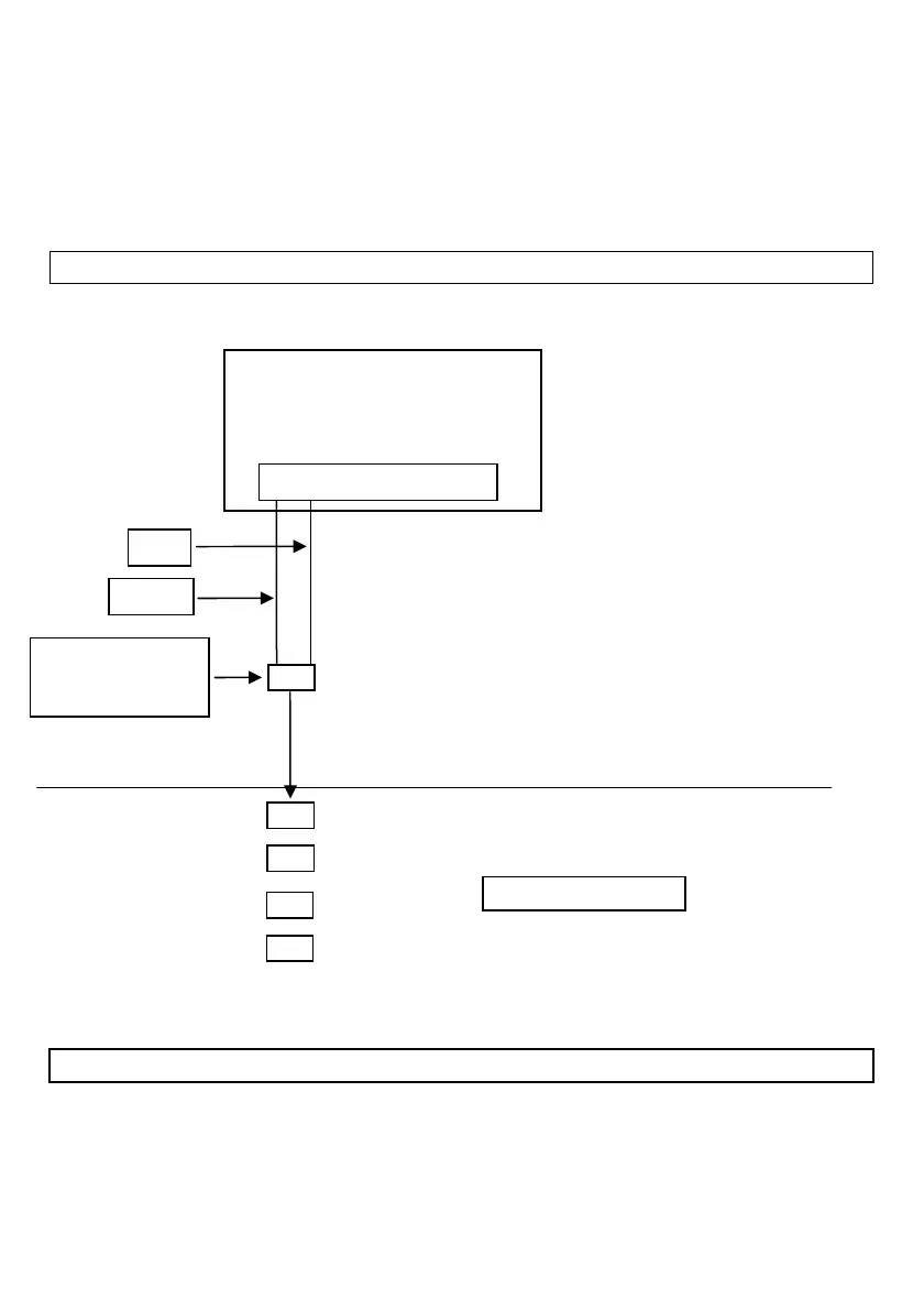
To test the alarm panel communication without using a telephone line, follow the connection and test
procedure in the example below
5.1.8
5.1.85.1.8
5.1.8
Line Listener Adapter
Line Listener AdapterLine Listener Adapter
Line Listener Adapter
This adapter enables easy access to a telephone line without having to open an equipment box or Venus
wall mounted socket. There are two methods
Get a Venus plug to double socket adapter, cut off the plug, strip about half of the PVC sleeving
off, cut off the black and yellow wires and connect banana plugs to the red and green wires.
L G L P P 1 2 3 4 5 6 7 8
e “Ultimate Communicator” format to 12 (Silent Knight 4x2 Fast)
2. Connect as shown
3. Initiate an “Event”
When the communicator LED switches on count 8 seconds then hold
down the [1] key on the keyboard for one second.
This will instruct “Line Card 1” to pick up the line and initiate an input
sequence.
The IDS BSR Display should show:
LC1 4/2 NP ACCT (Account Code) and XX (Event Code)
(RJ11 Telkom