IDS Base Station Receiver 400 700-179-02B Issued January 2009 5
Figures
FiguresFigures
Figures
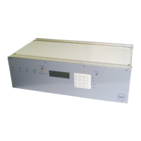
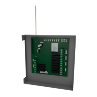
Figure 1 : IDS Base Station Receiver…………………………………………………………….…………….. 6
Figure 2 : IDS Base Station Receiver 400……………………………………………………………………….6
Figure 3 : IDS BSR400 Connection Diagram………………………………………………………….……....10
Figure 4 : IDS BSR Connection Diagram……………………………………………………………………....11
Figure 5 : IDS BSR400 System Grounding…………………………………………………………………….13
Figure 6 : Program Mode Menu Map………………………………………………………………………..…31
Tables
TablesTables
Tables
Table 1 : FORMAT Description……………………………………………………………………….………...25
Table 2 :TROUBLE Conditions………………………………………………………………………….……..26
Table 3 : Program Mode Menu…………………………………………………………………………….…...32
Table 4 : Format Out Options…………………………………………………………………………………..36
Table 5 : Printer Plain Library Format…………………………………………………………………..……....40
Table 6 : Printer Plain Library Codes………………………………………………………………………...…40
Table 7 : Event Type Buzzer Enable…………………………………………………………………….……..41
Table 8 : Contact ID [10x..42x] Event Type Buzzer Enable……………………………………………...…...42
Table 9 : Contact ID [44x..63x] Event Type Buzzer Enable……………………………………………….….42
Table 10 : Contact ID Group Event Codes……………………………………………….…………….….…..42
Table 11 : SIA [Ax..Px] Event Type Buzzer Enable………………………………………….…………….…..43
Table 12 : SIA [Qx..Zx] Event Type Buzzer Enable…………………………………………….………..….…43
Table 13 : SIA Group Event Codes………………………………………………………..……….…………..44
Table 14 : 3x1 and 4x1 Serial Event Code Identifier………………………………………………….……….48
Table 15 : 4x2 Serial Event Code Identifier……………………………………………………………….……48
Table 16 : 4x3 Serial Event Code Identifier…………………………………………….…………….………...48
Table 17 : Event Codes Identifiers………………………………………………………….…………………..48
Table 18 : Serial Out Options……………………………………………………………….…………………..49
Table 19 : Status Report Codes……………………………………………………………………………..…51
Table 20 : Line Card Option Bits……………………………………………………………………………….55