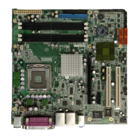
WAFER-LX Motherboard
Page vii
4.2.8 Floppy Disk Connector (Slim Type, Optional)................................................. 39
4.2.9 GPIO Connector.............................................................................................. 41
4.2.10 IDE Connector............................................................................................... 42
4.2.11 Inverter Power Connector.............................................................................. 43
4.2.12 Keyboard/Mouse Connector .......................................................................... 44
4.2.13 LED Connector.............................................................................................. 45
4.2.14 Print Port Connector ..................................................................................... 46
4.2.15 PC/104 Power Input Connector..................................................................... 47
4.2.16 PC/104 Slot.................................................................................................... 48
4.2.17 Reset Button Connector ................................................................................. 50
4.2.18 RS-232/422/485 Cable Connectors................................................................ 51
4.2.19 SATA Drive Connectors ................................................................................. 52
4.2.20 TFT LCD LVDS Connector............................................................................ 53
4.2.21 TFT LCD TTL Connector............................................................................... 55
4.2.22 Internal USB Connectors............................................................................... 56
4.3 EXTERNAL INTERFACE CONNECTORS ....................................................................... 57
4.3.1 External Interface Connector Overview .......................................................... 57
4.3.2 USB Combo Port.............................................................................................. 58
4.3.3 Ethernet Connector.......................................................................................... 58
4.3.4 Serial Communications COM 1 and COM2 Connector .................................. 59
4.3.5 VGA Connector................................................................................................ 60
5 INSTALLATION AND CONFIGURATION ............................................................ 62
5.1 ANTI-STATIC PRECAUTIONS ...................................................................................... 63
5.2 INSTALLATION CONSIDERATIONS.............................................................................. 63
5.2.1 Installation Notices.......................................................................................... 63
5.3 UNPACKING .............................................................................................................. 64
5.3.1 Unpacking Precautions.................................................................................... 64
5.3.2 Checklist........................................................................................................... 65
5.4 INSTALLATION PROCEDURE ...................................................................................... 65
5.4.1 DIMM Module Installation.............................................................................. 66
5.4.1.1 Purchasing the Memory Module............................................................... 66
5.4.1.2 DIMM Module Installation....................................................................... 67
5.4.2 Peripheral Device Connection......................................................................... 67
5.4.2.1 IDE Disk Drive Connector (IDE1) ........................................................... 68
 Loading...
