WAFER-LX Motherboard
Page 59
PIN DESCRIPTION PIN DESCRIPTION
1 TX+ 2 TX-
3 RX+ 4 NC
5 NC 6 RX-
7 NC 8 NC
Table 4-27: J7 Connector Pinouts
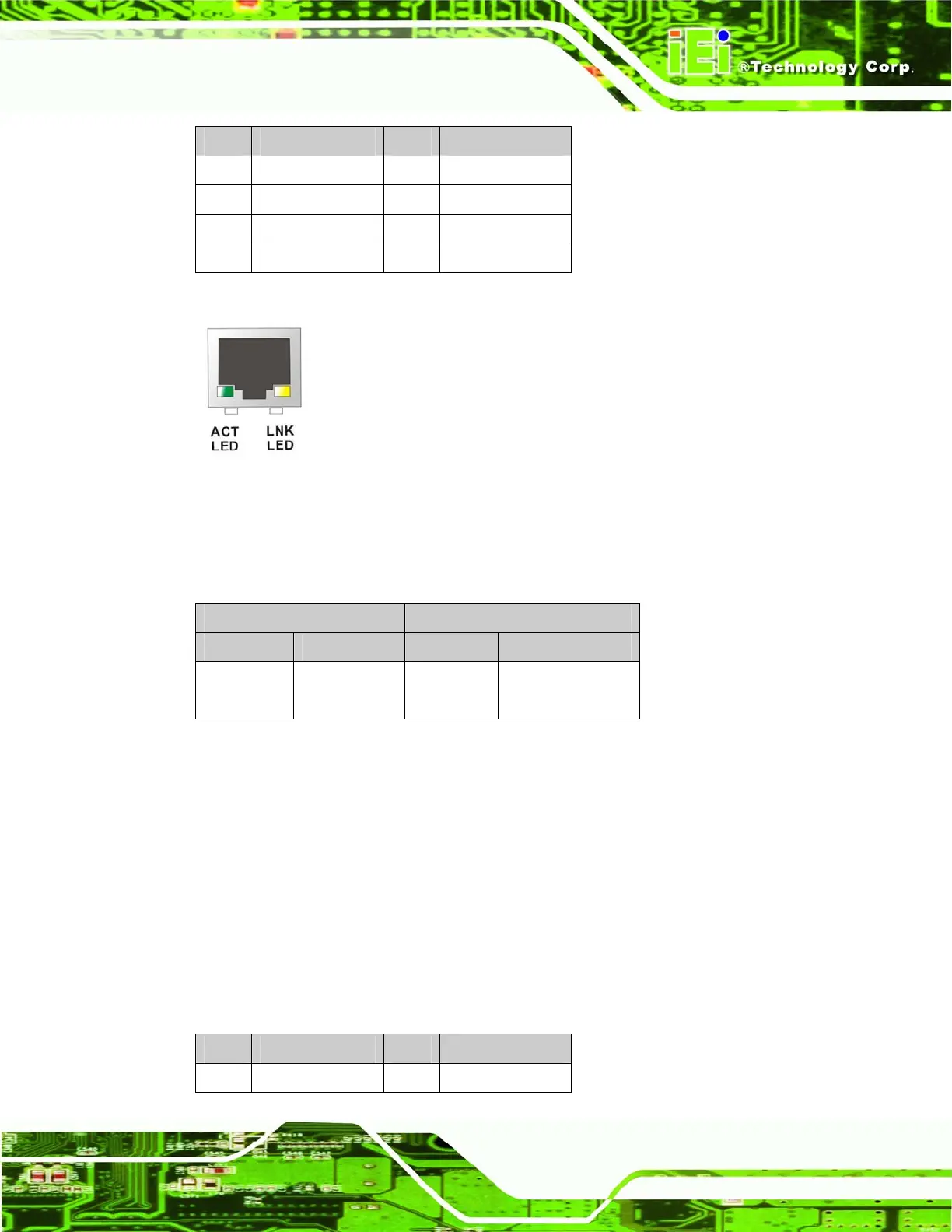
Figure 4-26: J7 Connector
The RJ-45 Ethernet connector has two status LEDs, one green and one yellow. The green
LED indicates activity on the port and the yellow LED indicates the port is linked.
SPEED LED LINK LED
Status Description Status Description
GREEN ON: 100 MB
OFF: 10 MB
YELLOW ON: Linked
Flashing: Activity
Table 4-28: J7 Connector LEDs
4.3.4 Serial Communications COM 1 and COM2 Connector
CN Label: CN22
CN Type:
RS-232 serial connector
CN Location:
See
Figure 4-25
CN Pinouts:
See
Table 4-29 and Figure 4-27
The RS-232 serial connector provides serial connection in the RS-232 mode.
PIN DESCRIPTION PIN DESCRIPTION
1 DCD1 2 RXD1

 Loading...


