EasyManua.ls Logo

Inovance MD500 User Manual

Inovance MD500
184 pages
To Next Page IconTo Next Page
To Previous Page IconTo Previous Page
Page #146 background imageLoading...
Page #146 background image
Appendix B
-
145
-
B.2 Modbus Communication Protocol
The drive provides RS485 communication interface and supports Modbus-RTU communication protocol, so
that the user can implement centralized control, such as setting running commands and function codes, and
reading running status and fault information of the AC drive, by using a PC or PLC.
This protocol denes content and format of transmitted messages during serial communication, including mas-
ter polling (or broadcasting) format and master coding method (function code for the action, transmission data,
and error check). The slave uses the same structure in response, including action conrmation, data returning
and error check. If an error occurs when the slave receives a message, or the slave cannot complete the action
required by the master, the slave returns a fault message as a response to the master.
B.2.1 Application
The AC drive is connected to a "single-master multi-slave" PC/PLC control network with RS485 bus.
B.2.2 Bus Structure
1. Interface mode
The RS485 extension card MD38TX1 must be inserted into the AC drive.
2. Topological structure
The system consists of a single master and multiple slaves. In the network, each communication device has a
unique slave address. A device is the master (can be a PC, a PLC or an HMI) and initiates communication to
perform parameter read or write operations on slaves. The other devices (slaves) provide data to respond to
query or operations from the master. At the same moment, either the master or the slave transmits data and
the other can only receives data.
The address range of the slaves is 1 to 247, and 0 is broadcast address. A slave address must be unique in the
network.
3. Transmission mode
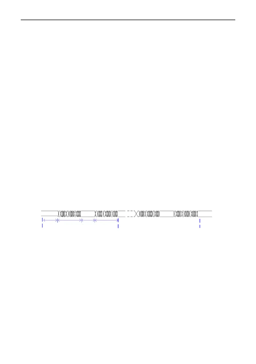
The asynchronous serial and half-duplex transmission mode is used. During asynchronous serial communica-
tion, data is sent frame by frame in the form of message. In Modbus-RTU protocol, an interval of at least 3.5-byte
time marks the end of the previous message. A new message starts to be sent after this interval.
Master sending 1 Slave response 1 Master sending 2 Slave response
2
Interval of at
least 3.5-byte
time
Interval of at
least 3.5-byte
time
Data frame
Data frame
A
B
The communication protocol used by the drive is the Modbus-RTU slave communication protocol, which allows
the drive to provide data to respond to "query/command" from the master or execute the action according to
"query/command" from the master.
The master can be a PC, an industrial device, or a PLC. The master can communicate with a single slave or
send broadcast messages to all slaves. When the master communicates with a single slave, the slave needs to
return a message (response) to "query/command" from the master. For a broadcast message sent by the mas-
ter, the slaves need not return a response.

Table of Contents

Questions and Answers:

Inovance MD500 Specifications

General IconGeneral
BrandInovance
ModelMD500
CategoryController
LanguageEnglish

Summary

Safety Information

Safety Precautions

General safety guidelines for installation, operation, and maintenance.

During Installation

Safety warnings and precautions specifically for installation.

During Wiring

Safety warnings and precautions related to wiring the AC drive.

During Power-on

Safety warnings and precautions for powering on the AC drive.

During Running

Safety warnings and precautions when the AC drive is in operation.

During Maintenance

Safety warnings and precautions for maintenance activities.

During Repair

Safety warnings and precautions related to repairing the AC drive.

System Connection

MD500 System Connection Diagram

Shows a schematic diagram of the AC drive and its peripheral devices.

Installation and Wiring

Installation

Covers general installation requirements and procedures for the AC drive.

Mounting Clearance and Orientation

Specifies required clearance and orientation for mounting the drive.

Mounting in Cabinet

Details installation requirements for mounting the drive inside a cabinet.

Wiring

Details the wiring procedures and diagrams for the AC drive.

Functions of Main Circuit Terminals and Precautions

Explains the functions of main circuit terminals and associated precautions.

Control Circuit Terminal Arrangement

Details the arrangement and functions of control circuit terminals.

Panel Operation

LED Operating Panel

Details the features and operation of the LED-type programming panel.

View and Modify Function Parameters

Explains the procedure for navigating and modifying function parameters.

View Function Parameters

Describes different modes for viewing function parameters and how to switch.

External LCD Operating Panel

Describes the appearance and features of the optional external LCD operating panel.

Basic Operations and Trial Run

Quick Commissioning Guide

Step-by-step guide for initial setup and trial run of the AC drive.

Commissioning Flowchart

Outlines the overall commissioning process in a flowchart format.

Checklist Before Power-on

A checklist of items to verify before powering on the AC drive.

Motor Control

Details the different motor control modes available (SVC, FVC, V/F).

Start/Stop running command

Describes methods for controlling the start and stop operations of the drive.

Start the AC Drive

Explains different start modes for the AC drive.

Auto-tuning

Explains the motor auto-tuning methods for obtaining motor parameters.

Troubleshooting and Solutions

Safety Information

Safety precautions specifically related to troubleshooting and maintenance.

Troubleshooting During Trial Run

Common problems and solutions encountered during the trial run phase.

Fault Display

Explains how faults are displayed and provides general solutions.

Resetting Fault

Details the methods for resetting faults on the AC drive.

Faults and Diagnostics

Lists common faults, their causes, and possible solutions.

Symptoms and Diagnostics

Describes common symptoms and provides diagnostic steps for troubleshooting.

Routine Inspection and Maintenance

Routine Inspection

General guidelines and safety precautions for routine inspection.

Definition of Communication Data Address and Modbus Communication Protocol

Related product manuals